Image processing apparatus, image processing method, and non-transitory computer-readable storage medium
a computer-readable storage medium and image processing technology, applied in the field of image processing apparatus, image processing method, and non-transitory computer-readable storage medium, can solve the problems of small influence of noise, small change such as noise, and high sensitivity noise when a digital camera performs capturing with increased sensor sensitivity. to achieve the effect of correcting contrast and suppressing the influence of nois
- Summary
- Abstract
- Description
- Claims
- Application Information
AI Technical Summary
Benefits of technology
Problems solved by technology
Method used
Image
Examples
first embodiment
[0022][System Configuration]
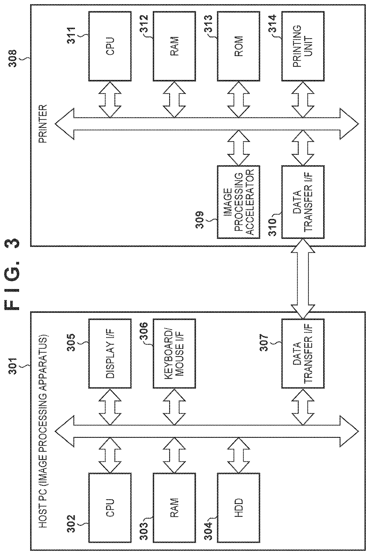
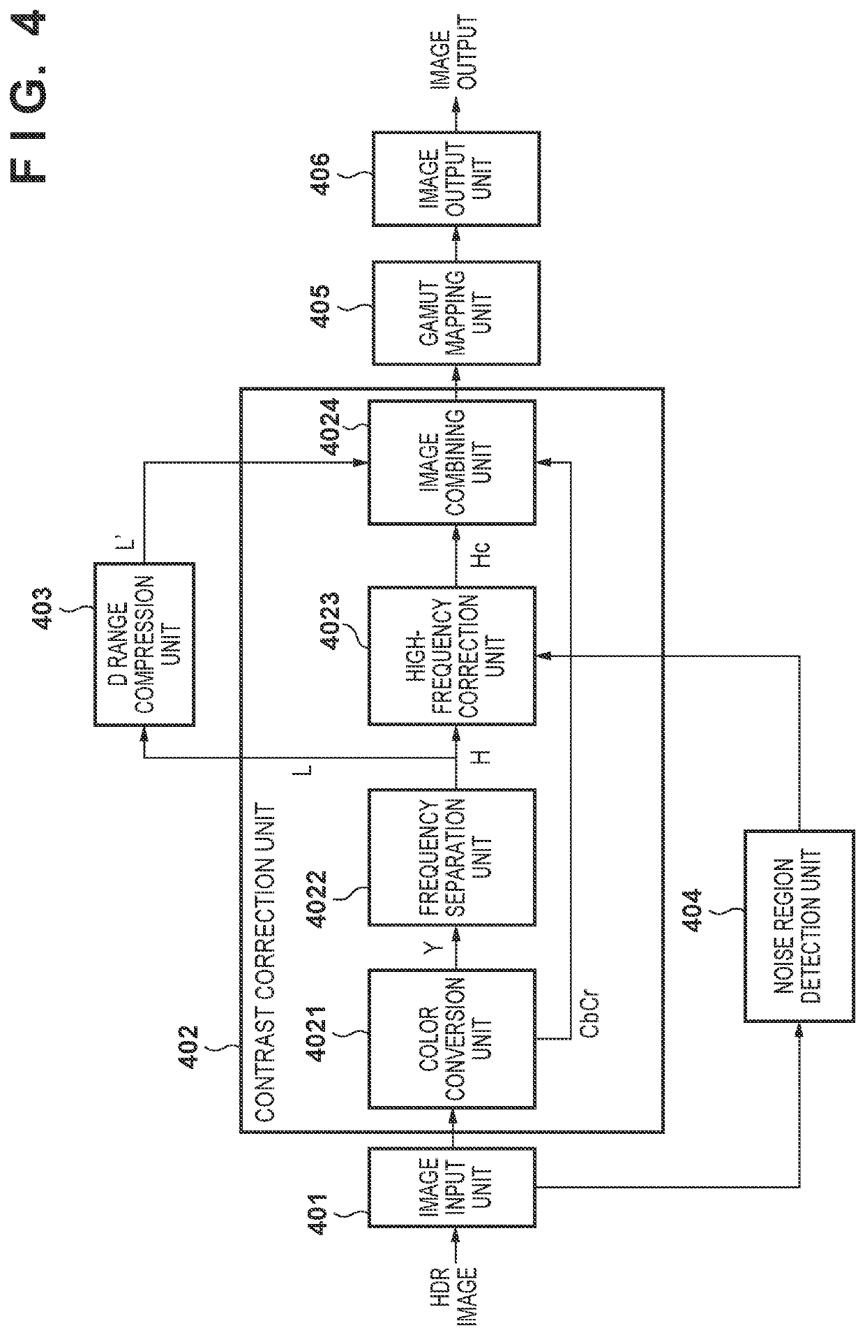
[0023]FIG. 3 is a diagram showing an example of a hardware configuration of a system in which the present invention can be used. In the present embodiment, the system is configured by including an image processing apparatus 301 as a host PC and a printer 308 as an image forming apparatus. The image processing apparatus 301 is configured by including a CPU (Central Processing Unit) 302, a RAM (Random Access Memory) 303, an HDD (Hard Disc Drive) 304, a display I / F (interface) 305, an input unit I / F 306, and a data transfer I / F 307. The CPU 302 executes various processes while using the RAM 303 as a work area in accordance with programs held in the HDD 304. For example, the CPU 302 generates image data that can be printed by the printer 308 in accordance with commands received from the user via the input unit I / F 306 and programs stored in the HDD 304. Then, the CPU 302 transfers the generated image data to the printer 308. Further, the CPU 302 performs pred...
second embodiment
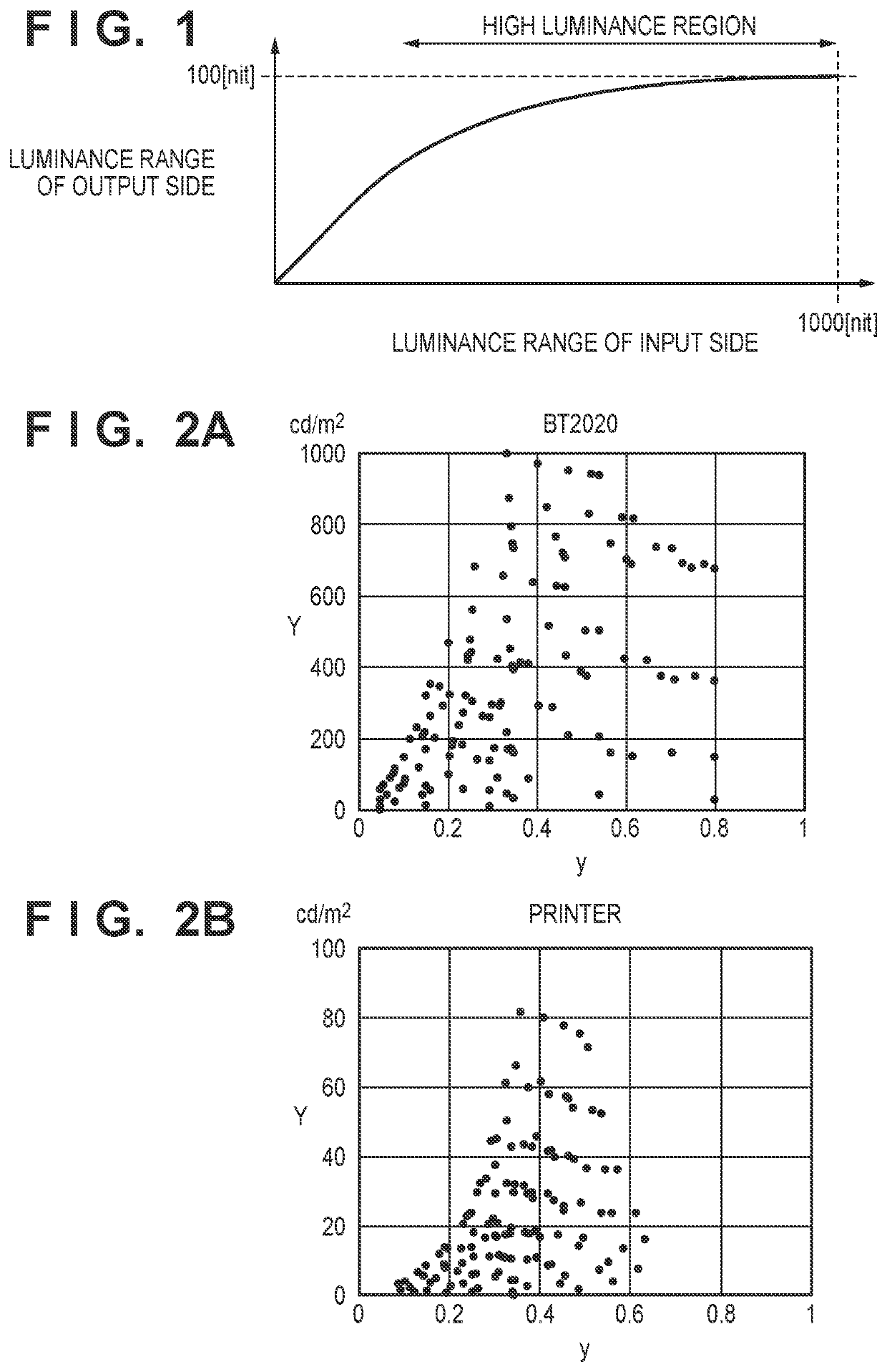
[0072]Description will be given regarding a second embodiment of the present invention. Image data subject to D range compression to the luminance range of an output device (printer) needs to be gamut-mapped to the color gamut of the output device. FIG. 2A and FIG. 2B are diagrams for describing the color gamut according to the present embodiment. FIG. 2A shows a color gamut of BT.2020 with a luminance range of 1000 nit. FIG. 2B shows a color gamut printed by a printer. In FIG. 2A and FIG. 2B, the horizontal axis represents the y of xy chromaticity, and the vertical axis represents luminance value. Comparing the BT.2020 color gamut with that of the printer, the color gamut shapes are not similar. When the shapes of the color gamut of the input image data and the color gamut of the printer are very different, for example, even if the contrast correction is performed by the method described in Japanese Patent Laid-Open No. 2011-86976, due to compression in accordance with gamut mappin...
third embodiment
[0099]Description will be given regarding a third embodiment of the present invention. Descriptions of portions overlapping with those of the first and second embodiments are omitted. In the first embodiment and the second embodiment, if the noise correction intensity Hn is less than 1.0, a noise suppression effect can be obtained. However, in order to further achieve a noise suppression effect in the bright portion of the image, it is necessary to change the noise correction intensity in accordance with the luminance value Y. The luminance value Y generated by the color conversion unit 4021 is used as the luminance value Y at this time. In the present embodiment, the noise correction intensity is determined for each pixel to be processed at a time of the processing of step S507 of FIG. 5 of the first embodiment or step S810 of FIG. 8 of the second embodiment.
[0100]The degree of change can be set by using the threshold luminance value Y2th and the maximum luminance value Y2max of th...
PUM
 Abstract
Description
Claims
Application Information
 - R&D
- Intellectual Property
- Life Sciences
- Materials
- Tech Scout
- Unparalleled Data Quality
- Higher Quality Content
- 60% Fewer Hallucinations
Browse by: Latest US Patents, China's latest patents, Technical Efficacy Thesaurus, Application Domain, Technology Topic, Popular Technical Reports.
© 2025 PatSnap. All rights reserved.Legal|Privacy policy|Modern Slavery Act Transparency Statement|Sitemap|About US| Contact US: help@patsnap.com


