Ultrasonic analysis of a subject

a subject and ultrasonic technology, applied in the field of non-destructive testing, can solve the problems of difficult setup and performance of ndt techniques, and/or may not perform well in detecting or characterizing the subtle properties of subjects

Active Publication Date: 2021-09-28
QUEENS UNIV OF KINGSTON +1
View PDF10 Cites 2 Cited by
  • Summary
  • Abstract
  • Description
  • Claims
  • Application Information

AI Technical Summary

Benefits of technology

[0004]In accordance with various embodiments, there is provided a method of facilitating ultrasonic analysis of a subject, the method involving producing signals for causing a set of outgoing ultrasonic signals to be transmitted to the subject, wherein the set of outgoing ultrasonic signals is defined at least in part by a variable imaging parameter that varies over time in accordance with a variable imaging parameter function, the variable imaging parameter function represented or representable at least in part by a function characteristic, receiving signals representing a time dependent representation of the subject generated from a set of received ultrasonic signals scattered by the subject, determining at least one property representation of the subject based on the function characteristic and the time dependent representation of the subject, and producing signals representing the at least one property representation of the subject to facilitate analysis of the subject.
[0018]In accordance with various embodiments, there is provided a system for facilitating ultrasonic analysis of a subject comprising at least one processor configured to perform any of the above methods.

Problems solved by technology

However, such known NDT techniques may be difficult to set up and perform and / or may not perform well in detecting or characterizing subtle properties of the subjects, such as, for example where a change in or loss of signal caused by the property may be negligible.

Method used


Image

  • Ultrasonic analysis of a subject
  • Ultrasonic analysis of a subject
  • Ultrasonic analysis of a subject

Examples


Embodiment Construction

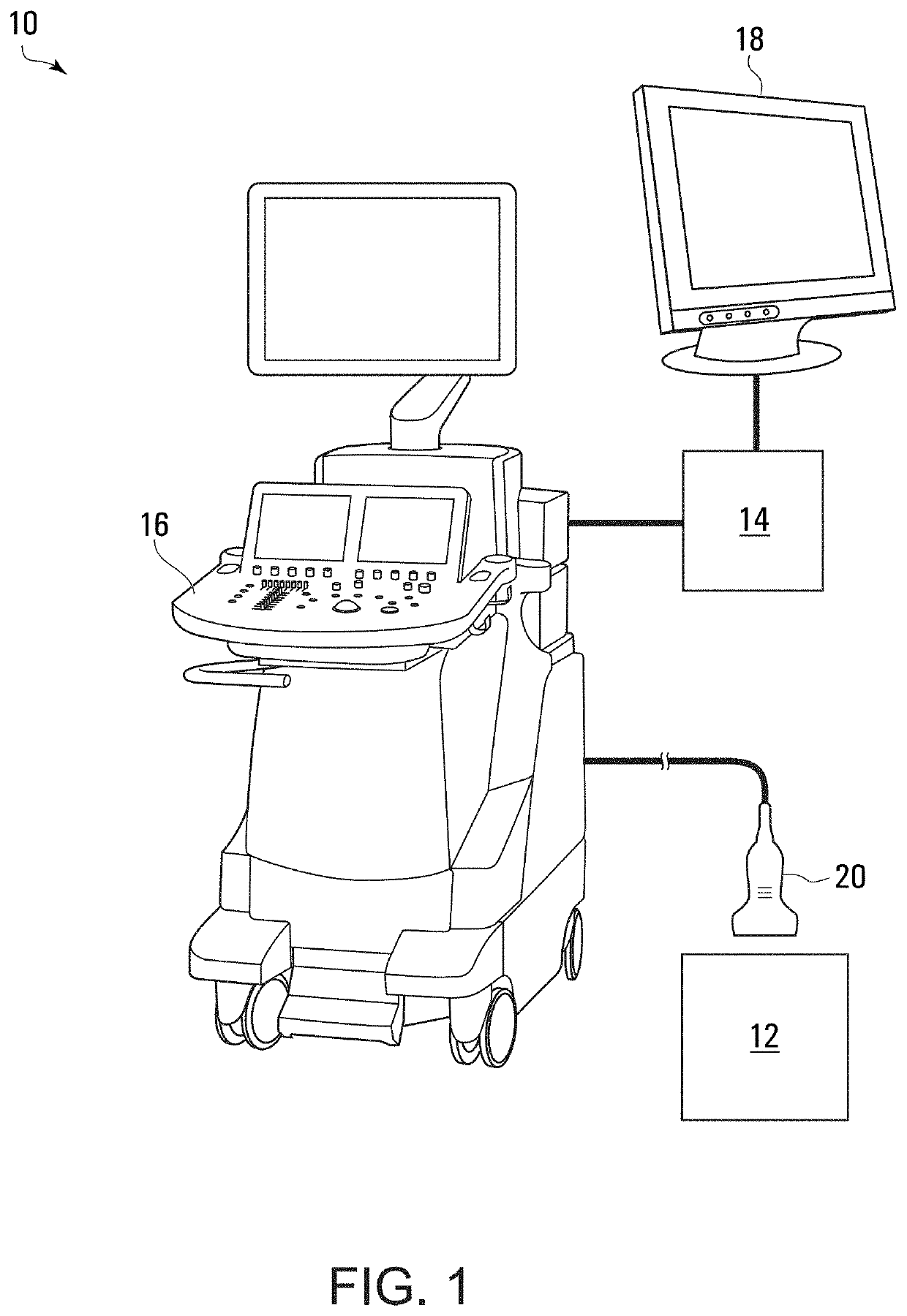
[0037]Referring to FIG. 1, there is provided a schematic representation of a system 10 for facilitating ultrasonic analysis of a subject 12, in accordance with various embodiments described herein. The system includes a computer-implemented analyzer 14 and an ultrasound machine 16 in communication with the analyzer 14. In various embodiments, the system 10 may also include a display 18 in communication with the analyzer 14.

[0038]In some embodiments, the system 10 may facilitate ultrasonic analysis of materials or parts to allow detection of subtle defects in the materials, which may be difficult to detect using conventional NDT analysis. In some embodiments, the system 10 may facilitate ultrasonic analysis of advanced composite parts, such as parts made from fiber-reinforced composite materials, for example. In various embodiments, defects may include, for example, porosity, foreign object debris, impact-induced delamination, heat-induced resin degradation, and / or waviness of fibers...


PUM

PropertyMeasurementUnit
mean focal depthaaaaaaaaaa

Abstract

A method of facilitating ultrasonic analysis of a subject is provided. The method involves producing signals for causing a set of outgoing ultrasonic signals to be transmitted to the subject, wherein the set of outgoing ultrasonic signals is defined at least in part by a variable imaging parameter that varies over time in accordance with a variable imaging parameter function, the variable imaging parameter function represented or representable at least in part by a function characteristic, receiving signals representing a time dependent representation of the subject generated from a set of received ultrasonic signals scattered by the subject, determining at least one property representation of the subject based on the function characteristic and the time dependent representation of the subject, and producing signals representing the at least one property representation of the subject to facilitate analysis of the subject. Systems, non-transitory computer readable media, and other methods are also provided.

Description

CROSS REFERENCES[0001]The following applications and materials are incorporated herein, in their entireties, for all purposes: U.S. Provisional Application No. 62 / 732,904 entitled “ULTRASONIC ANALYSIS OF A SUBJECT”, filed on Sep. 18, 2018; and International Application No. PCT / CA2019 / 051314, entitled “ULTRASONIC ANALYSIS OF A SUBJECT”, filed Sep. 16, 2019.BACKGROUND1. Field[0002]Embodiments of this present disclosure relate to nondestructive testing and more particularly to nondestructive testing using ultrasonic analysis of a subject.2. Description of Related Art[0003]Nondestructive Testing (“NDT”) may be used to analyze or characterize various subjects, such as, for example, materials, tissue, tools, devices, tissue / organs, or other subjects where damage to the subject is undesirable, but analysis of the subject is required. Some NDT techniques may involve using microscopy or analysis of a single ultrasound image. However, such known NDT techniques may be difficult to set up and p...

Claims


Application Information

Patent Timeline
Patent Type & Authority Patents(United States)
IPC IPC(8): G01N29/12G01N29/46G01N29/42
CPCG01N29/12G01N29/42G01N29/46G01N2291/015G01N2291/0231G01N2291/02818G01N2291/101G01N29/043G01N29/221G01N29/2456G01N29/0654A61B8/085A61B8/54A61B8/5207A61B8/462G01S7/52036G01S15/8915G01S7/5202
Inventor ABOLMAESUMI, PURANGMOUSAVI, PARVIN
Owner QUEENS UNIV OF KINGSTON
Why Eureka
Try Eureka