
System and method for passive assay of holdup deposits in nuclear piping

a holdup and nuclear pipe technology, applied in the direction of x/gamma/cosmic radiation measurement, instruments, dosimeters, etc., can solve the problems of difficult automation, labor-intensive methods, and gamma attenuation

Active Publication Date: 2021-10-05
CARNEGIE MELLON UNIV
View PDF9 Cites 0 Cited by
  • Summary
  • Abstract
  • Description
  • Claims
  • Application Information

AI Technical Summary

Benefits of technology

The invention is a novel system and method for measuring the isotopic composition of gaseous diffusion enrichment facilities using robotic disc-collimated measurements. This technology can provide significant cost and time savings, as well as reducing personnel exposure to radiation. It is particularly useful for measuring U-235, which can be determined accurately using scintillation spectrometers. The invention also allows for the safe and rapid deployment, operation, and maintenance of the robotic crawler in many pipes with minimal alteration to existing facility structure without requiring personnel at elevation during deployment.

Problems solved by technology

These methods are labor-intensive, subject to gamma attenuation by the walls of inspected pipes and challenging to automate.
Pipe wall signal attenuation, coupled with short count times, results in high uncertainty in individual measurements.
No satisfactory system has evolved for assaying holdup deposits by deploying detection apparatus internal to nuclear pipes.
However, such methods have many disadvantages, including manual deployment, attenuation by pipe walls, long counting time, approximate modeling, and shortfalls associated with transcription and human interpretation.
These downsides limit the quality, speed, pragmatics and economy of their application, resulting in an immense cost and schedule consequence to D&D.

Method used


Image

  • System and method for passive assay of holdup deposits in nuclear piping
  • System and method for passive assay of holdup deposits in nuclear piping
  • System and method for passive assay of holdup deposits in nuclear piping

Examples


Embodiment Construction

[0048]As used herein, the terms “robot”, “robotic apparatus” and “automated robotic platform” are used interchangeably.

Robotic Apparatus

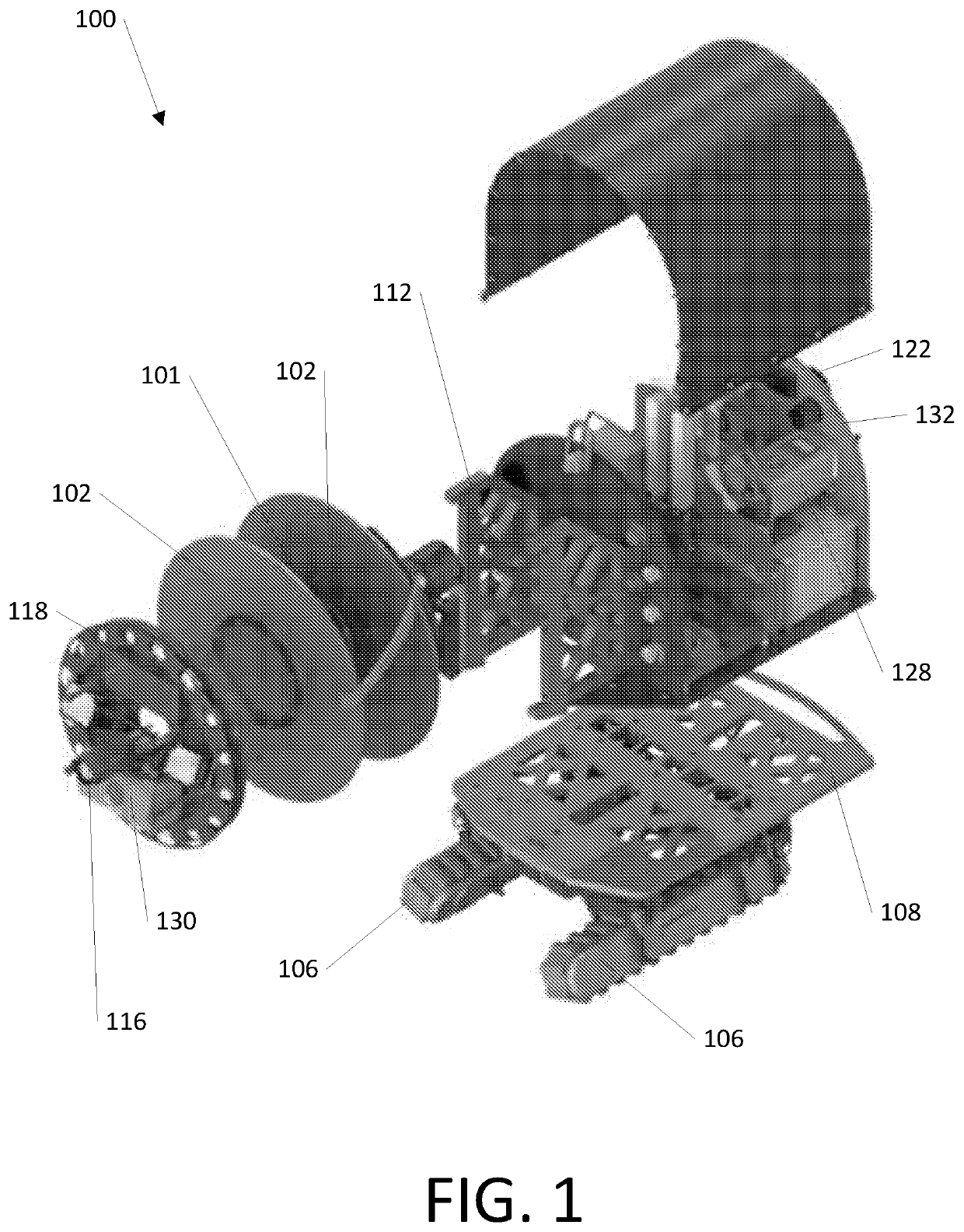
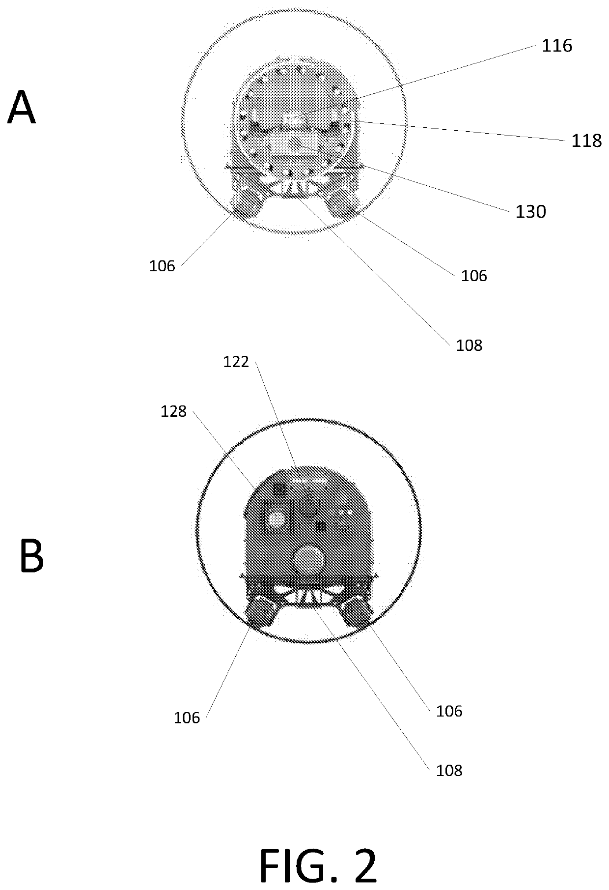
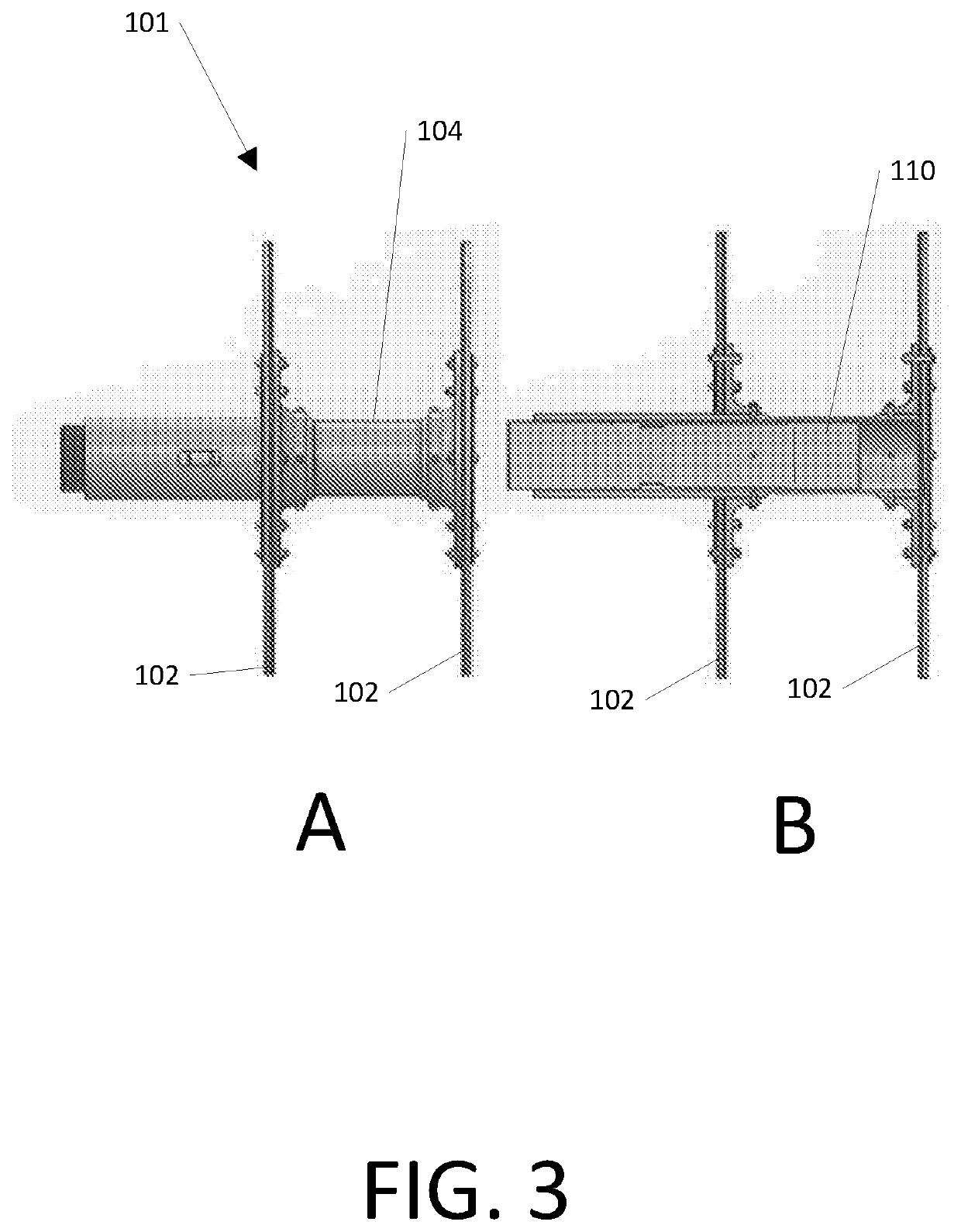
[0049]With reference to FIGS. 1-3, one aspect of preferred embodiments of the invention is a mobile robotic apparatus 100 supporting a disk-collimated detector assembly 101. In one embodiment, the full-sized robot 100 is sized to handle pipes having a diameter of about 30″ to 42″ and is approximately 1.2 meters long by 0.5 meters wide and 0.5 meters tall and weighs approximately 120 kg (260 lb.). The size of the robot can be scaled to handle larger or smaller pipes. In certain embodiments, pipes as small as about 3″ in diameter may be accommodated.

[0050]Robotic apparatus 100 moves through pipes on a platform 108 propelled by track modules 106 that maintain the axial centering of its disc-collimated detector 101 within the pipe. Track modules 106 incorporate encoders for providing odometry and respond to onboard computer commands based on an inertial...


PUM


Abstract

Disclosed herein are a method, apparatus, and software for passive, non-destructive assay of holdup deposits in nuclear piping by in-pipe apparatus. A detector deployed within a pipe is collimated to observe radiation impinging radially inward from decay of deposits that lie on the pipe wall. A radiation detector is centered in the pipe and collimated by a pair of coaxial shielding discs disposed equidistant from the detector. This arrangement causes radiation from a truncated cylinder of pipe deposit within a field of regard to impinge on the detector, while precluding radiation emanating from pipe walls beyond the field of regard from reaching the detector. Hence, observations are unique to a known cylindrical length of pipe. The detector assembly is translated through pipes by an autonomous mobile robotic apparatus. Computer software controls the robotic apparatus, logs data, and post-processes to assay deposits.

Description

RELATED APPLICATIONS[0001]This application is a national phase filing under 35 U.S.C. § 371 claiming the benefit of and priority to International Patent Application No. PCT / US2018 / 052245, filed on Sep. 21, 2018, which claims the benefit of U.S. Provisional Patent Application No. 62 / 606,421, filed Sep. 22, 2017. The entire contents of these applications are incorporated herein by reference.GOVERNMENT INTEREST[0002]This invention was made with government support under contract DEEM0004478 and DEEM0004383 awarded by the Department of Energy. The U. S. Government has certain rights in the invention.FIELD OF THE INVENTION[0003]This invention relates to a method for the nondestructive assay of holdup deposits in nuclear piping, and more particularly, to such a method and apparatus for autonomously measuring U-235 content in defunct enrichment facility gas diffusion piping.BACKGROUND OF THE INVENTION[0004]Efficiently determining holdup quantities of decaying isotopes in nuclear piping is r...

Claims


Application Information

Patent Timeline
Patent Type & Authority Patents(United States)
IPC IPC(8): G01T1/10G01V5/00G01T1/202
CPCG01V5/0091G01T1/202G01T1/00G01T7/00G01V5/281
Inventor WHITTAKER, WILLIAM LAWRENCEMALEY, SIRI KATRINAJONES, HEATHER LOUISESAPUNKOV, OLEG BORISOVICH
Owner CARNEGIE MELLON UNIV
Learn More