Antenna apparatus and electronic device comprising same

an antenna apparatus and electronic device technology, applied in the direction of individual energised antenna arrays, resonant antennas, particular array feeding systems, etc., can solve the problems of difficult tuning, ineffective connection structure of the first and second feed lines, and small antenna size, so as to improve the transmission insertion loss, reduce heat generation, and increase the antenna radiation efficiency

Active Publication Date: 2021-10-12
SAMSUNG ELECTRONICS CO LTD
View PDF53 Cites 0 Cited by
  • Summary
  • Abstract
  • Description
  • Claims
  • Application Information

AI Technical Summary

Benefits of technology

[0025]According to an embodiment of the present invention, it is possible to provide an antenna apparatus capable of reducing the heat generation and increasing the antenna radiation efficiency.
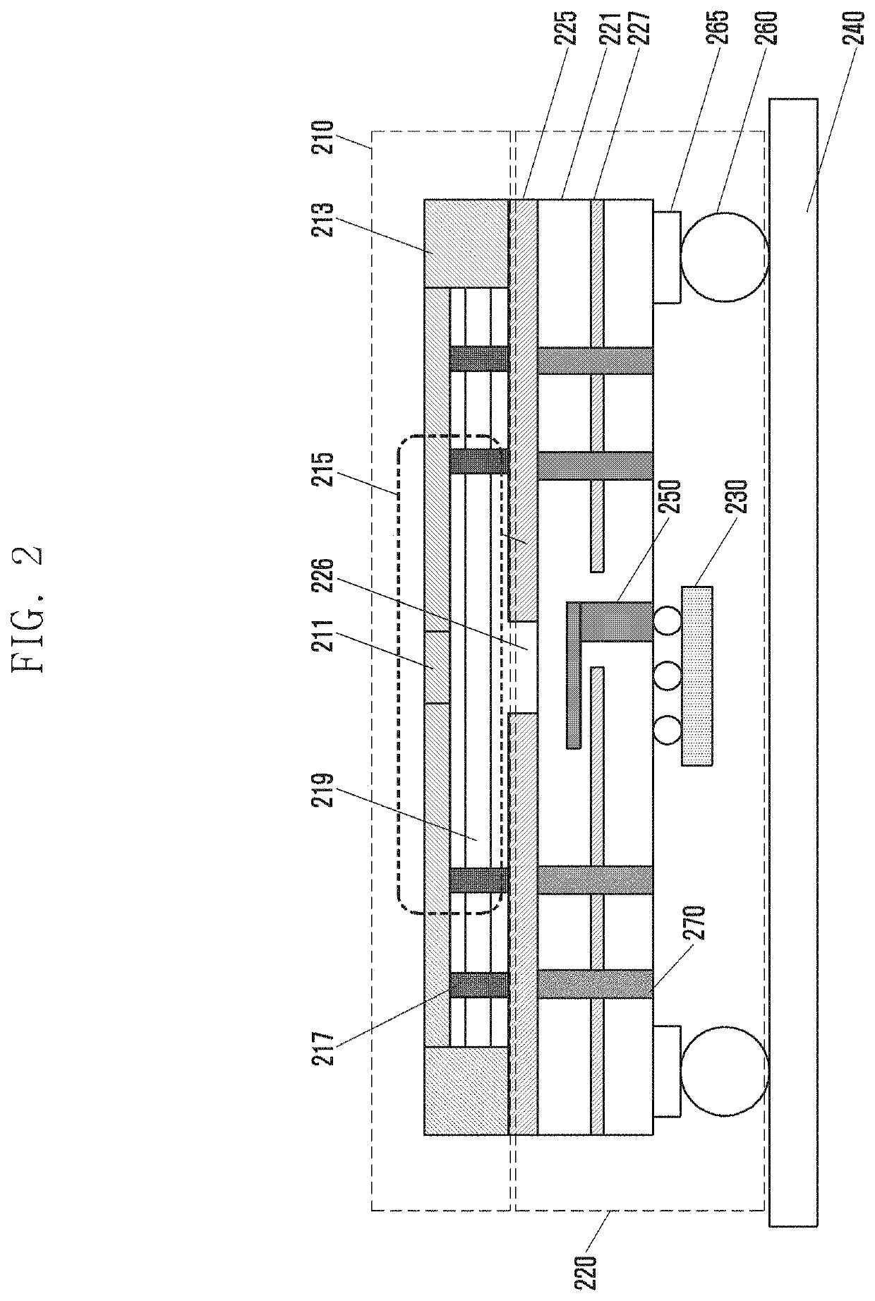
[0026]Also, the present invention can provide an antenna apparatus capable of improving a transmission insertion loss through an interleaved arrangement with external components.
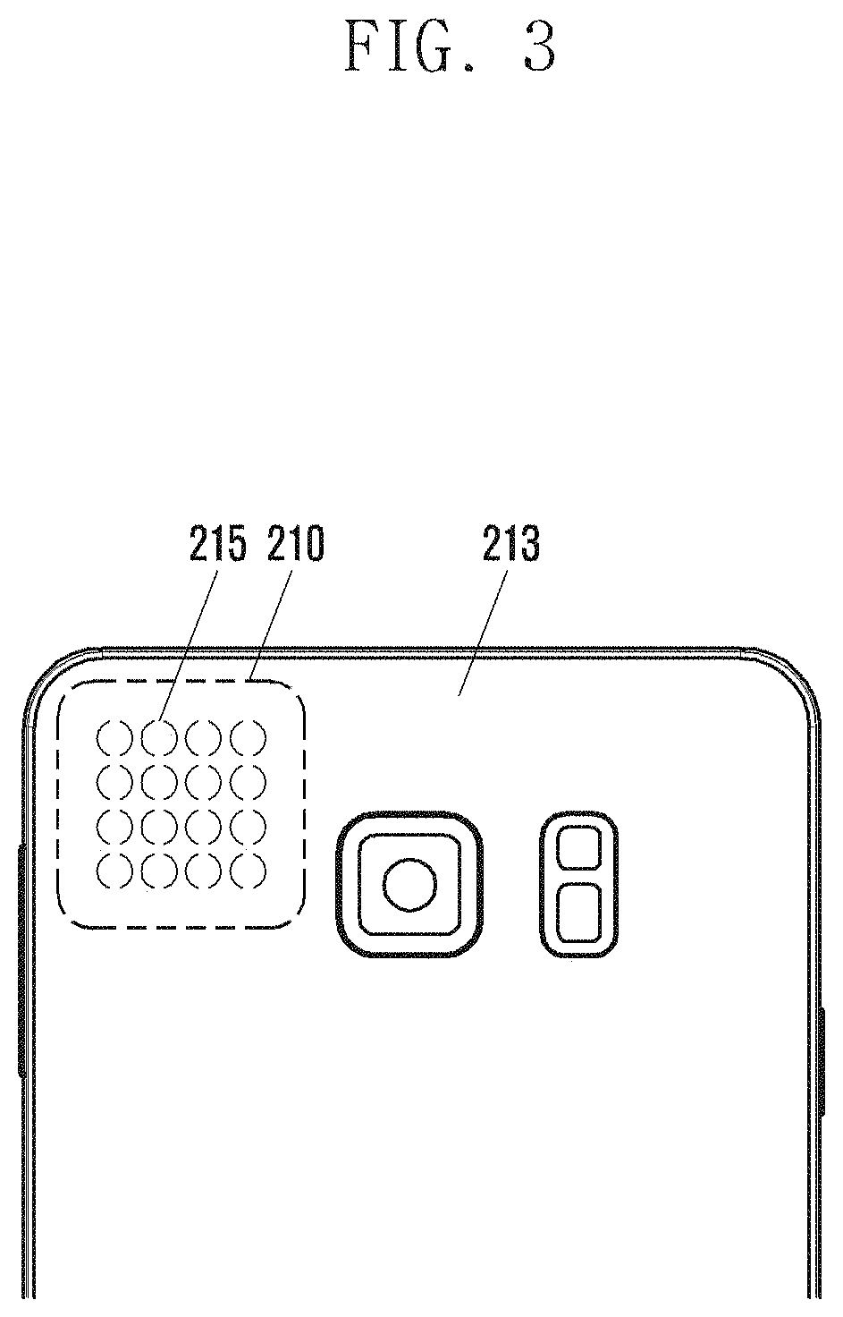
[0027]Further, the present invention can overcome limitations of antenna radiation limit by a metal case of an electronic device including an antenna apparatus.

Problems solved by technology

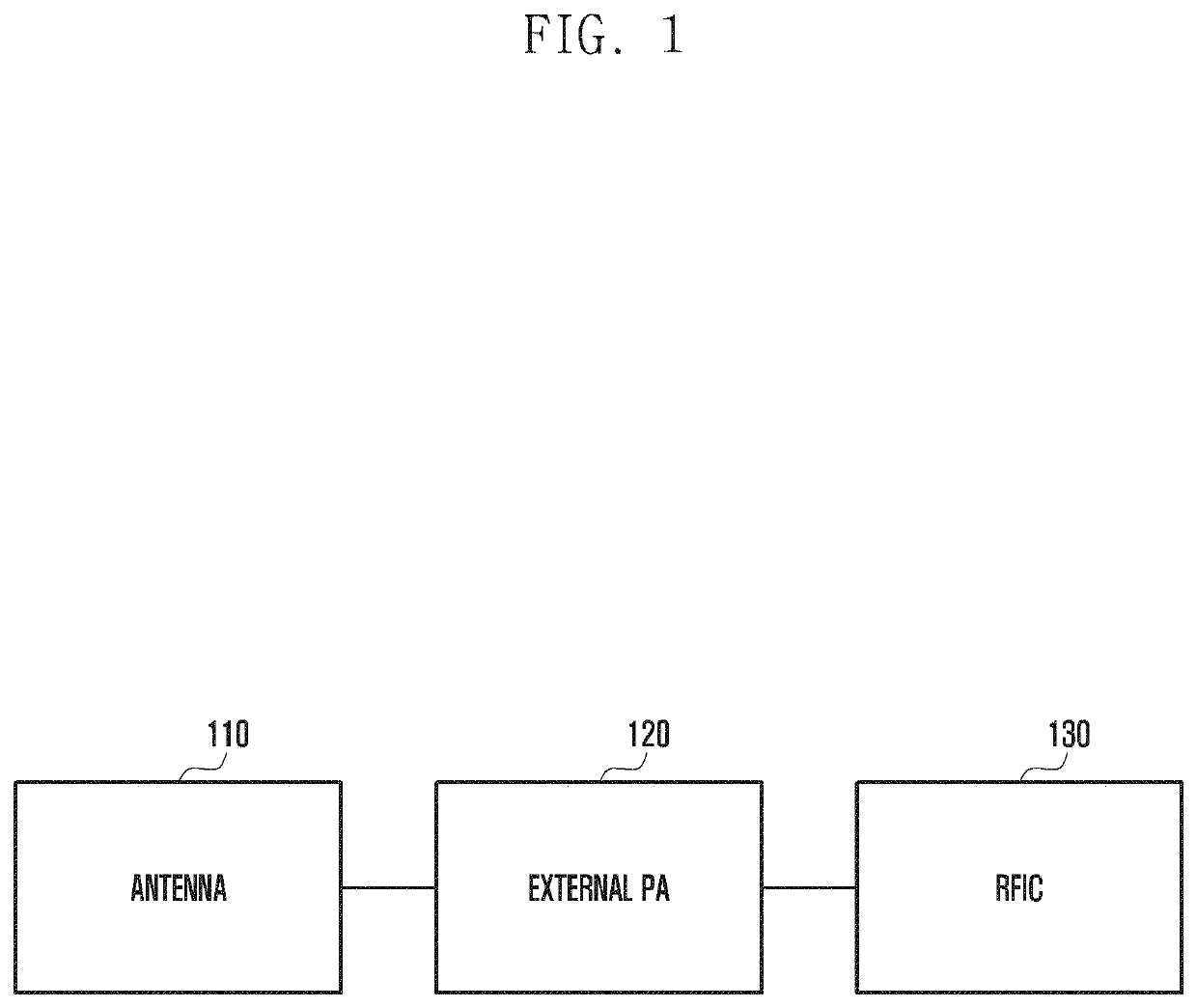
However, when the power amplifier is disposed around the array antenna and the RFIC is located under the array antenna, the connection structure of the first and second feed lines may be ineffective.
Also, in case of the super-high frequency band antenna that uses a resonance frequency of 28 GHz, the size of the antenna is very small, about 10 mm, and may cause difficult tuning.
Also, an antenna apparatus to which the multi-input multi-output (MIMO) is applied requires more feed lines connected to the antenna, and this may cause an increase in laminations of a substrate (e.g., PCB).
Besides, since there is a correlation between the height of the substrate and the bandwidth of the antenna, an antenna designed in limited substrate laminations may invite the degradation of performance.

Method used


Image

  • Antenna apparatus and electronic device comprising same
  • Antenna apparatus and electronic device comprising same
  • Antenna apparatus and electronic device comprising same

Examples


Embodiment Construction

[0054]Now, embodiments of the present invention will be described in detail with reference to the accompanying drawings. In the following description of embodiments, descriptions of techniques that are well known in the art and not directly related to the present invention are omitted. This is to clearly convey the subject matter of the invention by omitting any unnecessary explanation.

[0055]When it is stated that a certain element is “coupled to” or “connected to” another element, the element may be directly coupled or connected to another element, or a new element may exist between both elements. Also, the terms “include”, “comprise”, and “have” as well as derivatives thereof, mean inclusion without limitation.

[0056]In embodiments of the present invention, elements are shown independently to indicate different characteristic functions, but this does not mean that each element is formed of separate hardware or one software unit. That is, respective individual elements are merely fo...


PUM


Abstract

The present invention relates to an antenna apparatus and an electronic device comprising the same. The antenna apparatus according to one embodiment of the present invention comprises an array antenna formed on a metal case of an electronic device, wherein the array antenna comprises at least two antenna elements, the at least two antenna elements may operate in the same frequency band. According to one embodiment of the present invention, it is possible to provide an antenna apparatus capable of reducing heat generation and increasing the radiation efficiency of an antenna.

Description

TECHNICAL FIELD[0001]The present invention relates to an antenna apparatus and an electronic device including the same, and more particularly, to the antenna apparatus in which an array antenna is formed integrally with a metal case of the electronic device.BACKGROUND ART[0002]In order to satisfy the increasing demands of radio data traffic after the commercialization of a 4G communication system, efforts have been made to develop an advanced 5G communication system or a pre-5G communication system. For this reason, the 5G communication system or the pre-5G communication system is also referred to as a beyond-4G network communication system or a post-LTE system.[0003]In order to accomplish a higher data transfer rate, the implementation of the 5G communication system in a super-high frequency (mmWave) band (e.g., about a 28 GHz band) is being considered. Also, in order to obviate a propagation loss of a radio wave and increase a delivery distance of a radio wave in the super-high fr...

Claims


Application Information

Patent Timeline
Patent Type & Authority Patents(United States)
IPC IPC(8): H01Q1/02H01Q21/06H04M1/02H01Q9/04H01Q1/24H01Q21/00H04B1/44H01Q13/10
CPCH01Q1/02H01Q1/243H01Q9/0457H01Q21/0025H01Q21/064H01Q21/065H04B1/44H04M1/02H01Q13/10H01Q13/106H04M1/0202
Inventor BAEK, KWANGHYUNKIM, HYUNJINKIM, BYUNGCHULPARK, JUNGMINLEE, YOUNGJUHEO, JINSU
Owner SAMSUNG ELECTRONICS CO LTD
Why Eureka
Try Eureka