Versatile, flexible and biocompatible elastomeric microtubes

a biocompatible, flexible technology, applied in the field of elastomeric microtubes, can solve the problems of difficult to form complex three-dimensional (3d) microstructures, limit the geometry of microfluidic channels to rectangular cross-sections, etc., and achieve the effects of fast patterning of microchannels, reduced costs, and low cos

Active Publication Date: 2021-11-02
NAT UNIV OF SINGAPORE +2
View PDF21 Cites 1 Cited by
  • Summary
  • Abstract
  • Description
  • Claims
  • Application Information

AI Technical Summary

Benefits of technology

[0003]Novel, inexpensive and efficient methods to fabricate microfluidic tubes (microtubes) from a variety of elastomeric materials are described. These microtubes have an inner diameter that can range from about 4 μm to about 1000 μm and an outer diameter that is variable and can be controlled depending on needs. The length of the microtubes can be varied depending on the end use. The microtubes can have any desired cross-sectional shape, for example, circular, rectangular, square, triangular, elliptical, star or irregular. Using these elastomeric microtubes as basic building blocks, it is now possible to design and produce microfluidic devices without the need for photolithography. This not only radically changes the way one designs and builds microfluidic devices, but also provides the versatility to alter the design of the microfluidic devices at will without the need to redesign and refabricate the whole microfluidic device again. Instead, these microtubes can be added or removed to make changes to the design of the microfluidic device which can be in two-dimensional (2D) or even 3D in configuration. The ability of these elastic microtubes to be assembled and disassembled enables the fast patterning of microchannels into almost any architecture as needed and when desired. Consequently, significant reductions in costs have been seen, as well as a significant reduction in the time taken to design, build and test these microfluidic devices. In addition, the microtubes can be biocompatible, flexible, gas permeable and highly transparent and make for an excellent candidate for producing biomedical devices for various applications, e.g., flexible microfluidics, artificial skins, organs-on-chips, blood vessel and capillary network mimicking, opto-microfluidics and 3D bioreactors, among others.

Problems solved by technology

However, the conventional fabrication of microfluidics always involves the complicated photolithography process which is expensive, limits microfluidic channel geometry to rectangular cross-section and is difficult to form complex three-dimensional (3D) microstructures.
All these pose a barrier for the wider adoption of this technique.

Method used


Image

  • Versatile, flexible and biocompatible elastomeric microtubes
  • Versatile, flexible and biocompatible elastomeric microtubes
  • Versatile, flexible and biocompatible elastomeric microtubes

Examples


example 1

Making Silicone Elastomer Based Microtube

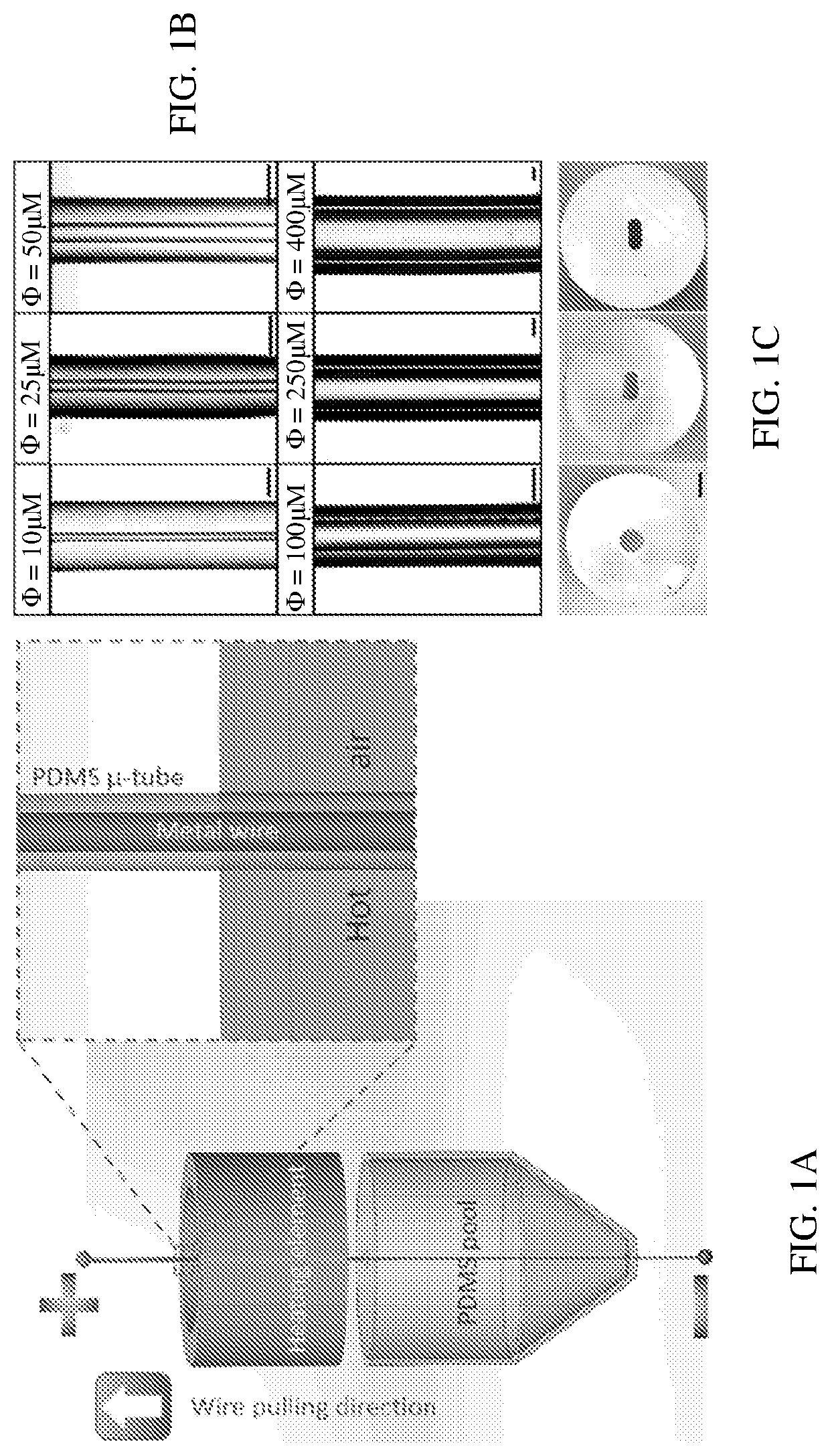
[0069]The method involves immersing a metal wire (normally made of copper or tungsten) vertically into a freshly mixed PDMS (mixture of Sylgard 184 silicone elastomer base and Sylgard 184 silicone elastomer curing agent, 10:1 by weight) or a UV sensitive polymer (MYpolymer, MY-134-XP8, MY Polymers Ltd.) pool, as depicted in FIG. 1A. To fabricate PDMS microtubes, the metal wire was then connected to a variable power supply and heated up to ˜100° C. by electricity for 3-5 minutes. This generates a heat field close to the metal wire that initiate PDMS curing. A thin layer of cured PDMS forms on the surface of the wire and its thickness depends on the heating period. The metal wire was then pulled out of the PDMS pool at a speed of ca. 200 μm / s vertically above the fluid level by a linear stepping motor, and a second thin layer of viscous uncured PDMS will form around the wire, which is further cured by hot air at ca. 90-100° C. in a cylindrical ...

example 2

ive Polymer Based Microtube

[0072]To fabricate MYpolymer microtubes, the metal wire was pulled out of a pre-cured UV-curable MYpolymer pool into an Ar chamber. The thin MYpolymer layer coated around the metal wire was then cured on-site under a UV mercury lamp (350-460 nm, Newport Oriel Product Line System) operating at 300 W with an illumination power of 0.2 W / cm2. The MYpolymer coated metal wire was then transferred into a pure ethanol bath and sonicated for 30 minutes to remove the diffusing photoinitiator. The MYpolymer microtubes (FIG. 4) can then detach from the metal wires after the ethanol treatment, followed by baking in a 100° C. oven for one hour to remove any ethanol remnant.

[0073]The mechanical properties of the PDMS microtubes are characterized and listed below when compared with commercially available silicone tubing:

[0074]

PropertyUnitSiliconePDMS microtubesTensile strengthMPa6.8-8.7 5-10Elongation at break%570-795200-400HardnessShoreA: 50-80A: 43Brittle temperature° C...

example 3

otubes as Basic Microfluidic Components (Pipe, Valve and Pump)

[0077]The PDMS cured under our experimental condition normally has a Young's modulus of 1.5-2.0 MPa, allowing significant deflections with moderate actuation forces. This property then provides a unique solution for the valving and actuation for microtube-based microfluidic devices. Flows in these microtubes can be easily controlled merely via mechanical compression and release on them by a commercially available mechanical pincher on the pipeline (FIGS. 6A and 6B). Microtubes with circular cross-section were used for the implementation of valving due to the fact that the rounded channels close from edges to center by external compressional force and thus seal completely at lower pressure in comparison to rectangular and square channels.11 The control of flows with an on-off valve is demonstrated in FIG. 6A. The mechanical pinch point that crosses over the microtubes is normally 0.5 mm in the width and for a microtube wit...


PUM

PropertyMeasurementUnit
outer diameteraaaaaaaaaa
inner diameteraaaaaaaaaa

Abstract

The present invention relates to a flexible polymer-based microtube having an inner diameter of about 4 μm to about 1000 μm and a variable outer diameter, wherein the cross-sectional shape of the microtube can be, for instance, circular, rectangular, square, triangular, elliptical, star or irregular. The present invention also relates to a method of making the flexible microtube and devices incorporating the flexible microtube.

Description

RELATED APPLICATION[0001]This application claims the benefit of U.S. Provisional Application No. 62 / 302,919 filed on Mar. 3, 2016. The entire teachings of the above application are incorporated herein by reference.BACKGROUND[0002]Microfluidics devices made of elastomeric materials such as polydimethylsiloxane (PDMS) normally consist of microfluidic channels specifically designed to perform tasks such as microscale manipulation, analysis and sorting of micro and nanoscale entities such as biomolecules, cells and particles. However, the conventional fabrication of microfluidics always involves the complicated photolithography process which is expensive, limits microfluidic channel geometry to rectangular cross-section and is difficult to form complex three-dimensional (3D) microstructures. All these pose a barrier for the wider adoption of this technique.SUMMARY OF THE INVENTION[0003]Novel, inexpensive and efficient methods to fabricate microfluidic tubes (microtubes) from a variety o...

Claims


Application Information

Patent Timeline
Patent Type & Authority Patents(United States)
IPC IPC(8): B29C41/14B81C1/00A61L27/60A61L27/18A61L27/50B29C41/42C08L15/00C08L75/04C08L79/08C08L83/04C12M3/06A61F2/10B29L31/00
CPCB81C1/00134A61L27/18A61L27/50A61L27/507A61L27/60B29C41/14B29C41/42C08L15/00C08L75/04C08L79/08C08L83/04A61F2/105B29K2995/0026B29K2995/0056B29K2995/0065B29L2031/7532B81C2201/038C08L2203/02C12M23/16A61L27/56
Inventor XI, WANGLIM, CHWEE TECKKONG, FANGGONG, XIAOBO
Owner NAT UNIV OF SINGAPORE
Why Eureka
Try Eureka