Traceable optical device

a traceable optical and handle technology, applied in the field of traceable optical devices, can solve the problem that the feature points of the handle are always difficult to be detected, and achieve the effect of efficient solving

Active Publication Date: 2021-11-23
HTC CORP
View PDF46 Cites 0 Cited by
  • Summary
  • Abstract
  • Description
  • Claims
  • Application Information

AI Technical Summary

Benefits of technology

[0006]An aspect of the disclosure is to provide a traceable optical device that can efficiently solve the aforementioned problems.
[0027]Accordingly, in the traceable optical device of the present disclosure, after the light source emits light into the light guide member, the light can be transmitted in the light guide member and uniformly leave the light guide member from the light-emitting surface thereof. The light leaving the light guide member passes through the light transmission area of the shielding member to be detected. As such, the traceable optical device can provide a traceable optical feature with high brightness contrast which can be easily identified, so that the location and / or orientation of the traceable optical device can be easily determined. Moreover, by using the light guide member to transmit the light emitted from the light source and uniformly distribute the light leaving from the light-emitting surface thereof, the need to increase the number of the light source can be greatly reduced, so that the traceable optical device is low in electrical power loss.

Problems solved by technology

However, when being held in front of a high-intensity light source in a dim environment, the feature points of the handle are always hard to be detected.
Accordingly, it is an important issue for the industry to provide a traceable optical device capable of solving the aforementioned problems.

Method used


Image

  • Traceable optical device
  • Traceable optical device
  • Traceable optical device

Examples


Embodiment Construction

[0043]Reference will now be made in detail to the present embodiments of the disclosure, examples of which are illustrated in the accompanying drawings. Wherever possible, the same reference numbers are used in the drawings and the description to refer to the same or like parts. However, specific structural and functional details disclosed herein are merely representative for purposes of describing example embodiments, and thus may be embodied in many alternate forms and should not be construed as limited to only example embodiments set forth herein. Therefore, it should be understood that there is no intent to limit example embodiments to the particular forms disclosed, but on the contrary, example embodiments are to cover all modifications, equivalents, and alternatives falling within the scope of the disclosure.

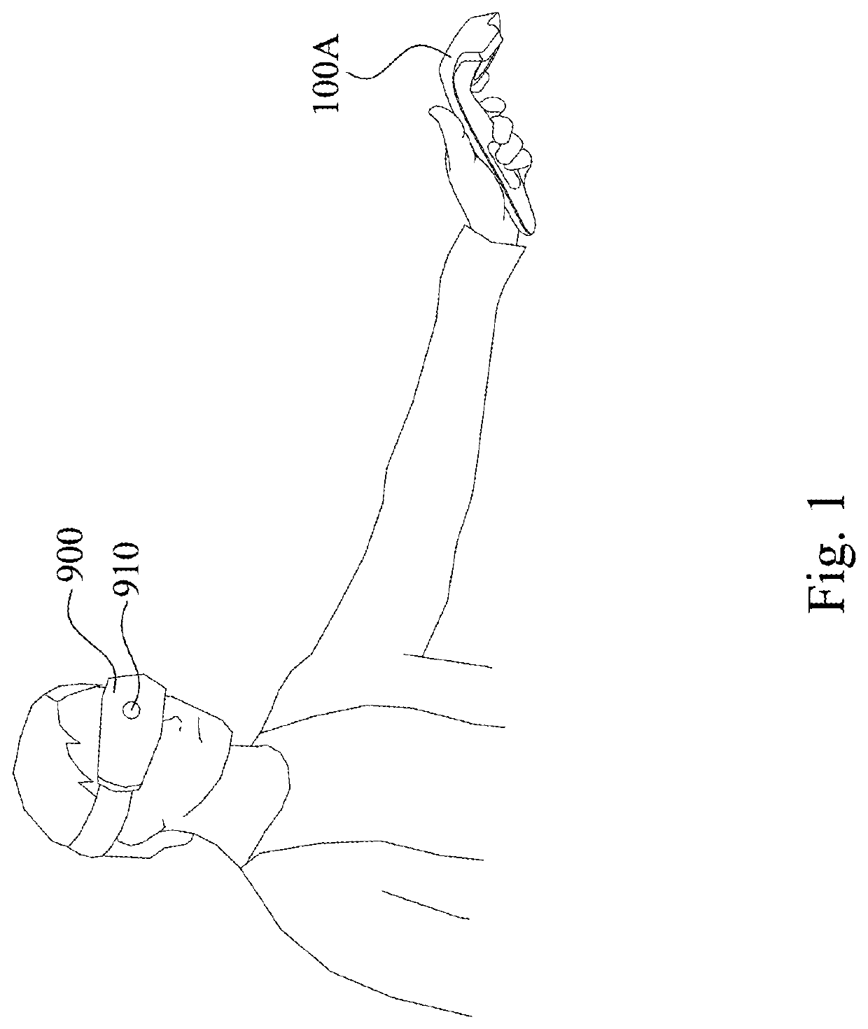
[0044]Reference is made to FIG. 1. FIG. 1 is a schematic view illustrating a user interacting with a head-mounted display (HMD) 900 and a traceable optical device 100A acc...


PUM

PropertyMeasurementUnit
light transmissionaaaaaaaaaa
refractive indicesaaaaaaaaaa
refractive indexaaaaaaaaaa

Abstract

A traceable optical device is capable of being tracked by an electronic device having an image sensor. The traceable optical device includes a light guide member, at least one light source, and a shielding member. The light guide member has at least one light-incident surface and a light-emitting surface connected to each other. The light source is configured to emit light into the light guide member from the light-incident surface. The shielding member shields the light guide member and has at least one light transmission area.

Description

CROSS-REFERENCE TO RELATED APPLICATION[0001]This application claims priority to U.S. Provisional Application Ser. No. 62 / 635,557, filed on Feb. 27, 2018, which is herein incorporated by reference.BACKGROUNDTechnical Field[0002]The present disclosure relates to an electronic device, and more particularly, to a traceable optical device.Description of Related Art[0003]One of the rapidly growing technologies in the field of human-computer interaction is various head-mounted displays (HMDs), which may be worn on a user's head and have one or two displays in front of the user's eyes. This type of display has multiple commercial applications involving simulation of virtual reality including video games, medicine, sport training, entertainment applications, and so forth. In the gaming field, these displays may be used, for example, to render three-dimensional (3D) virtual game worlds.[0004]Nowadays, computer vision methods, in particular, object tracking, are widely used in various applicat...

Claims


Application Information

Patent Timeline
Patent Type & Authority Patents(United States)
IPC IPC(8): G06F3/038A63F13/235G02B27/01G06F3/01G06F3/03G06F1/16A63F13/213G06F3/0346A63F13/24A63F13/833A63F13/26G08C23/04
CPCG06F3/0383A63F13/213A63F13/235A63F13/24A63F13/26A63F13/833G02B27/0172G06F1/163G06F1/1686G06F3/011G06F3/017G06F3/0325G06F3/0346A63F2300/1031A63F2300/8082G02B27/017G06F2203/0384G08C23/04G08C2201/32A63F13/25A63F2300/1087A63F2300/30
Inventor DENG, QING-LONGCHANG, LI-HSUN
Owner HTC CORP
Why Eureka
Try Eureka