
Battery system, electrically-powered vehicle and control method for electrically-powered vehicle

a technology of electrical power and battery system, which is applied in the direction of battery/fuel cell control arrangement, secondary cell servicing/maintenance, electrochemical generators, etc., can solve the problems of vehicle traveling in an impossible state, reducing fuel economy, and affecting the efficiency of electric power generation, so as to reduce fuel economy and effectively utilize electric power

Active Publication Date: 2021-11-23
TOYOTA JIDOSHA KK
View PDF3 Cites 0 Cited by
  • Summary
  • Abstract
  • Description
  • Claims
  • Application Information

AI Technical Summary

Benefits of technology

The patent text describes a method for improving the efficiency of power usage in an electric vehicle. The method involves two stages of equalization control: one when the vehicle is in a traveling-possible state, and another when it is in a traveling-impossible state. By using a converter instead of a resistor, the method reduces generation of heat and allows for effective utilization of electric power. This ensures a consistent supply of electric power to the auxiliary device for a long period of time. The technical effect of the patent text is the improved efficiency of power usage in electric vehicles.

Problems solved by technology

Therefore, when the electrically-powered vehicle is a hybrid vehicle, an adverse effect on the equalization control, such as reduction in fuel economy, may occur.
It is also assumed that the vehicle is in a traveling-impossible state for a long period of time, such as the vehicle being left unattended for several months.
Therefore, electric power stored in the auxiliary battery can possibly decrease excessively and the function of the auxiliary device cannot possibly be maintained.
Furthermore, since the auxiliary battery is charged, the electric power required for the auxiliary device can be supplied for a long period of time.

Method used


Image

  • Battery system, electrically-powered vehicle and control method for electrically-powered vehicle
  • Battery system, electrically-powered vehicle and control method for electrically-powered vehicle
  • Battery system, electrically-powered vehicle and control method for electrically-powered vehicle

Examples


embodiment

[0026]

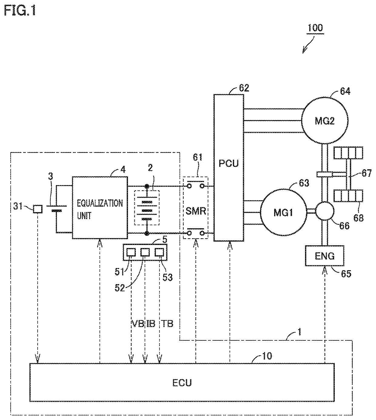
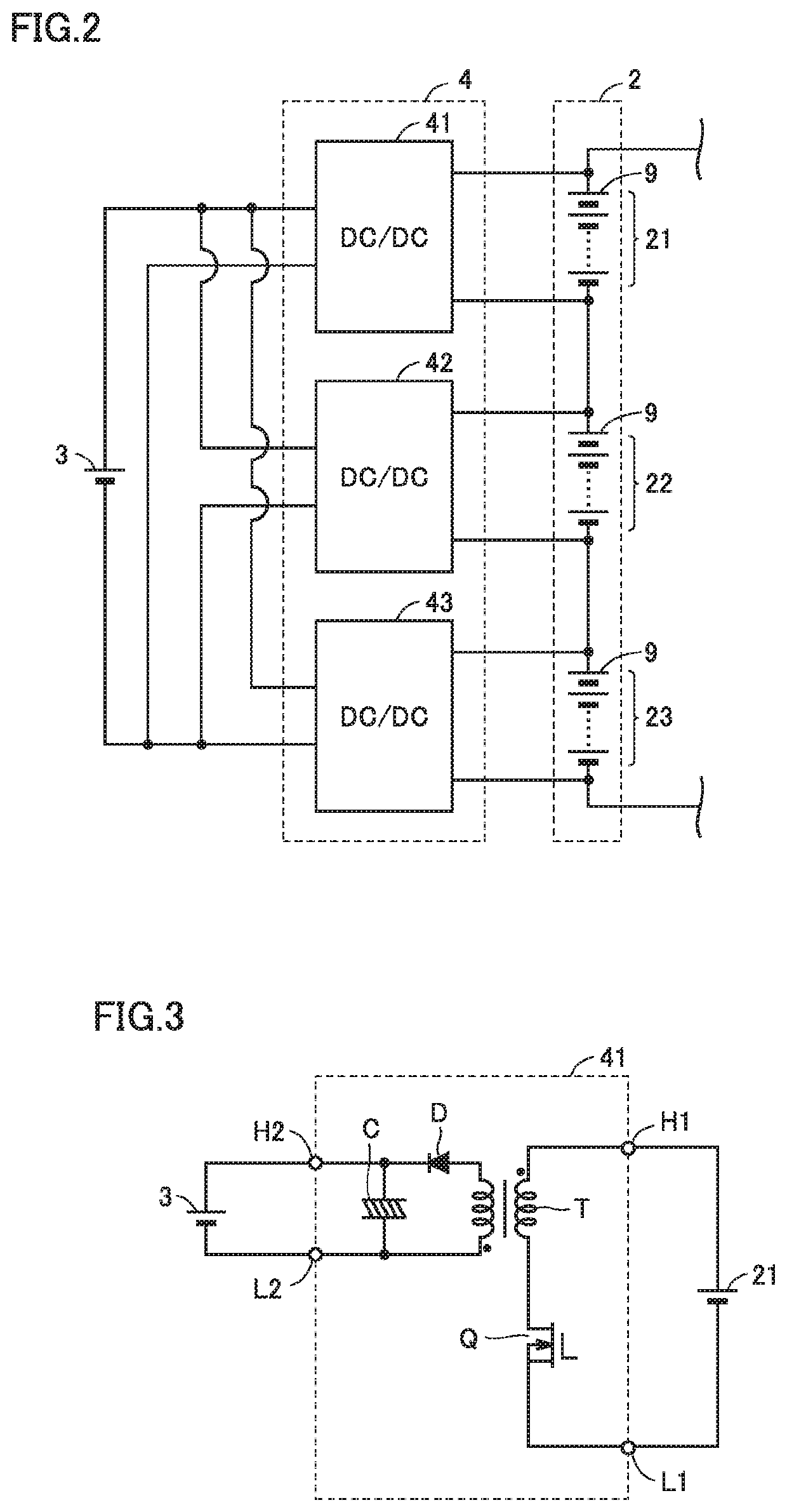
[0027]FIG. 1 is a block diagram schematically showing an overall configuration of a vehicle according to the present embodiment. Referring to FIG. 1, a vehicle 100 is, for example, a hybrid vehicle and includes a battery system 1. Battery system 1 includes a battery pack 2, an auxiliary battery 3, an equalization unit 4, a monitoring unit 5, and an electronic control unit (ECU) 10. In addition to battery system 1, vehicle 100 further includes a system main relay (SMR) 61, a power control unit (PCU) 62, motor generators 63 and 64, an engine 65, a power split device 66, a drive shaft 67, and a driving wheel 68.

[0028]Battery pack 2 stores electric power for driving motor generators 63 and 64, and supplies the electric power to motor generators 63 and 64 through PCU 62. An output voltage of battery pack 2 is, for example, approximately several hundred volts. In addition, battery pack 2 receives generated electric power through PCU 62 during power generation by motor generators 63 ...


PUM


Abstract

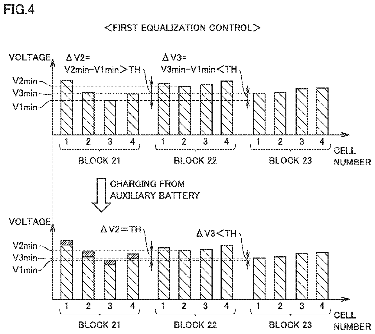
A battery system includes a plurality of converters wherein each converter converts an electric power between a corresponding block of a plurality of blocks and an auxiliary battery. A first equalization control is a control for, when a vehicle is in a ReadyON state, operating a converter corresponding to a lower-voltage block, of at least one pair of blocks of the plurality of blocks having voltage variations exceeding a threshold value, such that the lower-voltage block is charged with an electric power supplied from the auxiliary battery. A second equalization control is a control for, when the vehicle is in a ReadyOFF state, operating a converter corresponding to a higher-voltage block, of at least one pair of blocks of the plurality of blocks having the voltage variations exceeding another threshold value, such that the auxiliary battery is charged with an electric power supplied from the higher-voltage block.

Description

[0001]This nonprovisional application is based on Japanese Patent Application No. 2018-235383 filed on Dec. 17, 2018 with the Japan Patent Office, the entire contents of which are hereby incorporated by reference.BACKGROUNDField[0002]The present disclosure relates to a battery system, an electrically-powered vehicle and a control method for the electrically-powered vehicle, and more particularly, to the charging and discharging technique in a battery system mounted on an electrically-powered vehicle including an auxiliary device and a motor serving as a driving source.Description of the Background Art[0003]In recent years, electrically-powered vehicles (hybrid vehicles or electric vehicles) on which assembled batteries for supplying electric power to motors serving as driving sources are mounted have been becoming popular. Some of the assembled batteries mounted on these electrically-powered vehicles have a configuration described below. Specifically, the assembled battery includes ...

Claims


Application Information

Patent Timeline
Patent Type & Authority Patents(United States)
IPC IPC(8): H02J7/00B60L58/20H02J7/34
CPCH02J7/0014B60L58/20H02J7/342B60L58/18B60L58/22H01M10/425H01M10/4207H01M10/441B60L2240/547H02J7/1423H02J7/0018H02J2310/48Y02T10/7072Y02T90/14B60L2210/10Y02T10/72Y02T10/70
Inventor TANAKA, HIROMASA
Owner TOYOTA JIDOSHA KK
Learn More