
Method of creating a flexible circuit

a flexible circuit and circuit technology, applied in the direction of printed circuit non-printed electric components association, printed element electric connection formation, conductive pattern formation, etc., can solve the problems of inconvenient manufacturing process, high contact resistance between integrated circuit components and conductive elastomers, inaccurate heart rate measurement, etc., to achieve high flexibility and stretchability, ideal for comfort and usability

Active Publication Date: 2021-11-23
CARNEGIE MELLON UNIV
View PDF15 Cites 2 Cited by
  • Summary
  • Abstract
  • Description
  • Claims
  • Application Information

AI Technical Summary

Benefits of technology

This patent describes a flexible circuit that uses a conductive polymer layered with a polymer base. The circuit components are connected to the conductive polymer through elongated electrical contacts, which reduce contact resistance. The flexible circuit can be manufactured using a mold and conductive epoxy, and it is ideal for use in wearable devices due to its low-cost and flexibility. The main technical effect is an improved interconnection between circuit components that allows for complex circuits to be created.

Problems solved by technology

With rigid devices, the lack of flexibility can cause issues with data acquisition, since the interface between the non-flexible device and flexible skin is not ideal.
For example, wrist-worn general wellness devices, such as fitness watches, can suffer from inaccurate heart rate measurements due to movement of the device relative to the skin.
However, the contact resistance between the integrated circuit components and conductive elastomer can be prohibitively high, particularly after stretching the device.
Other attempts have used liquid conductors or meandering wires rather than a conductive elastomer, but these techniques can require expensive manufacturing processes, such as the sputter deposition of copper.
While these examples demonstrate flexible circuits, the ability to incorporate non-flexible circuit components is marginal and the costs of these techniques can be prohibitive to commercial-scale manufacturing.

Method used


Image

  • Method of creating a flexible circuit
  • Method of creating a flexible circuit
  • Method of creating a flexible circuit

Examples


Embodiment Construction

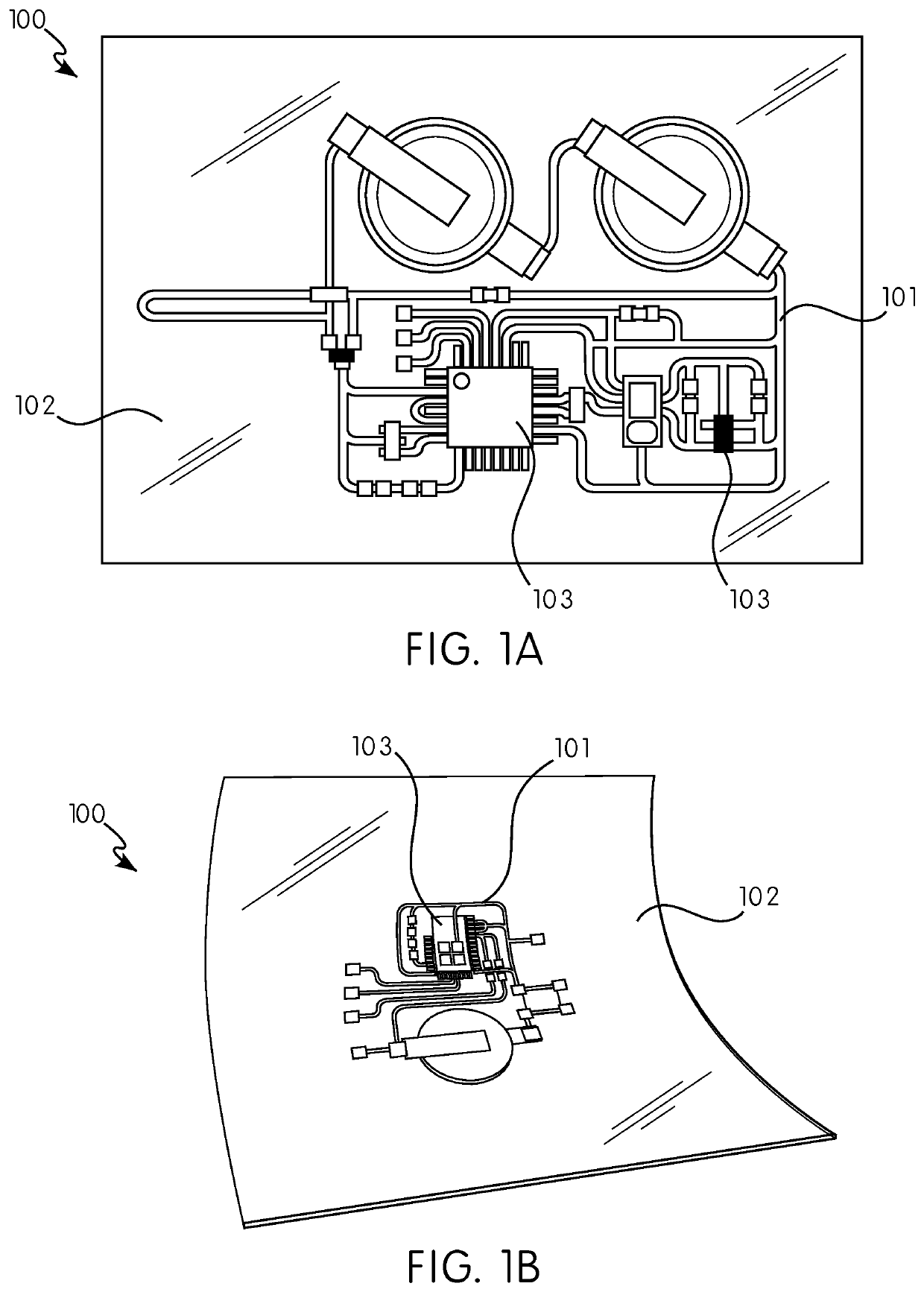
[0013]According to certain embodiments, the flexible circuit 100 comprises a conductive polymer 101, a flexible base 102, and at least one integrated circuit component 103. FIG. 1A shows an example of a flexible circuit 100 used as a heart monitor, where the conductive polymer 101 is visible on a surface of the flexible base 102. FIG. 1B demonstrates the flexibility of another example circuit 100, with the flexible base 102 and conductive polymer 101 bending in a curve. During the manufacturing process, the conductive polymer 101 and flexible base 102 are bonded together, providing support for the relatively thin lines of conductive polymer 101. Further shown in FIGS. 1A-1B are several integrated circuit components 103, in electrical contact with the conductive polymer 101.

[0014]In the example embodiments shown in FIGS. 1A-1B, an electrically conductive silver / polydimethylsiloxane material is used as the conductive polymer 101, where silver filler-particles are dispersed within the ...


PUM

PropertyMeasurementUnit
flexibleaaaaaaaaaa
conductiveaaaaaaaaaa
electricalaaaaaaaaaa

Abstract

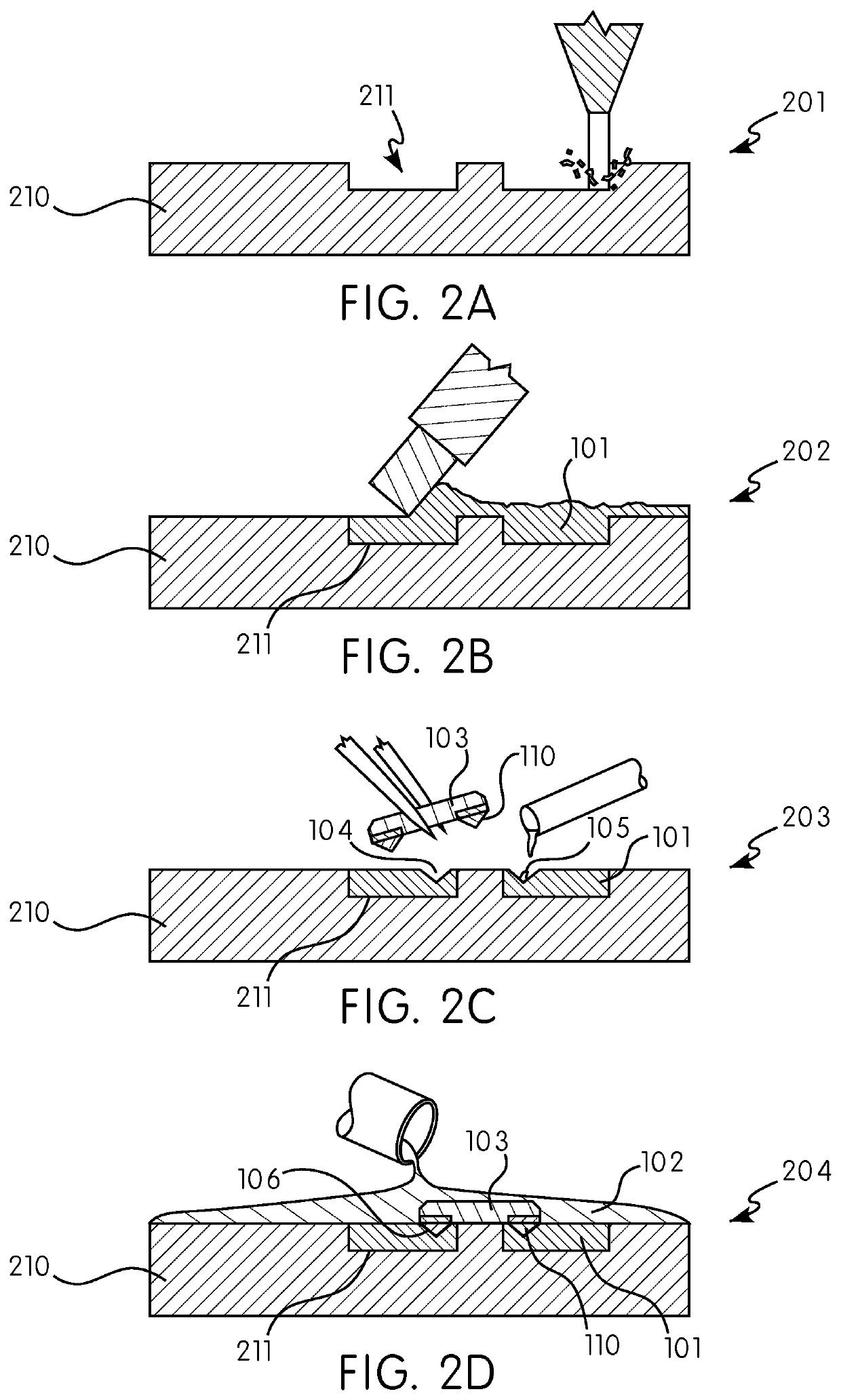
According to one embodiment is a flexible circuit comprising a flexible base, a conductive polymer supported by the base, and an integrated circuit component having an elongated electrical contact, wherein the elongated electrical contact penetrates into the conductive polymer, thereby providing a robust electrical connection. According to methods of certain embodiments, the flexible circuit is manufactured using a molding process, where a conductive polymer is deposited into recesses in a mold, integrated circuit components are placed in contact with the conductive polymer, and a flexible polymer base is poured over the mold prior to curing. In an alternative embodiment, a multiple-layer flexible circuit is manufacturing using a plurality of molds.

Description

CROSS-REFERENCE TO RELATED APPLICATIONS[0001]This application claims the benefit under 35 U.S.C. § 119 of Provisional Application Ser. No. 62 / 499,868, filed Feb. 6, 2017, and Provisional Application Ser. No. 62 / 602,364, filed Apr. 20, 2017, each of which is incorporated herein by reference.STATEMENT REGARDING FEDERALLY SPONSORED RESEARCH[0002]This invention was made with government support under U.S. Army No. W81XWH-16-C-0186. The government has certain rights in this invention.BACKGROUND OF THE INVENTION[0003]The invention relates to a flexible circuit. More specifically, the invention relates to a flexible circuit that incorporates rigid components such as resistors, capacitors, wireless-enabled microprocessors, or other integrated circuit components. The invention further relates to a method of making the flexible circuit.[0004]Flexible circuits have many uses, including as sensors adapted to be worn in contact with the skin of a user. For example, a wearable, flexible circuit ca...

Claims


Application Information

Patent Timeline
Patent Type & Authority Patents(United States)
IPC IPC(8): H05K1/02H05K1/09H05K1/18H05K3/00H05K3/10H05K3/34H05K3/40H05K3/46
CPCH05K1/0277H05K1/09H05K1/185H05K3/0014H05K3/107H05K3/34H05K3/4038H05K3/4644H05K2201/0215H05K2201/0329H05K1/188H05K1/189H05K3/1258H05K3/321H05K2203/0156
Inventor CHARALAMBIDES, ALEXANDROSMAJIDI, CARMEL
Owner CARNEGIE MELLON UNIV
Learn More