Automatic cleaning device for suction port of electric submersible pump

a technology of automatic cleaning and suction port, which is applied in the direction of machines/engines, liquid fuel engines, borehole/well accessories, etc., can solve the problems of affecting the efficiency of electric submersible pumps, so as to achieve the effect of reducing the viscosity of heavy oil, simple structure and automatic cleaning of the suction por

Active Publication Date: 2021-11-30
SOUTHWEST PETROLEUM UNIV
View PDF3 Cites 0 Cited by
  • Summary
  • Abstract
  • Description
  • Claims
  • Application Information

AI Technical Summary

Benefits of technology

[0006]The purpose of the present invention is to provide an automatic cleaning device for suction port of electric submersible pump to overcome the shortcomings of prior arts. This device is driven by the electric submersible pump to realize automatic cleaning. Based on the pressure difference between the outlet of electric submersible pump and the suction port, it depends on the water jet and self-excited vibration cavitation effect of the nozzle to effectively realize scale prevention, plug removal and viscosity reduction of suction port and also reduce such risks as shutdown, pump jamming and well failure, etc.
[0016]After the produced high-pressure fluid is ejected from the nozzle, it directly acts on the suction port of the electric submersible pump to realize effective plug removal and scale prevention under its jet action, vibration wave and cavitation action. The oscillation and cavitation effects of vibration wave break the medium and long molecular chains of crude oil, reduce the viscosity of crude oil and facilitate the suction of the electric submersible pump, making the electric submersible pump more suitable for heavy oil production.
[0017]Due to a significant pressure difference between the outlet of the electric submersible pump and the suction port, as long as the electric submersible pump works normally, part of the produced high-pressure fluid can be ejected from the nozzle to realize real-time automatic cleaning of the suction port. When the electric submersible pump stops, the produced fluid pressure of electric submersible pump drops, and the check valve is automatically closed, so as to avoid the backflow of fluid in the bottom well through the nozzle and the connecting pipe.
[0018]The present invention has the following beneficial effects and advantages:
[0019]1. The present invention can automatically clean the suction port of the electric submersible pump by relying on the pressure difference between the outlet and the suction port of the electric submersible pump. 2. Depending on the water jet and self-excited vibration cavitation effect of the nozzle, the present invention can effectively reduce the viscosity of heavy oil and realize scale prevention and plug removal. 3. The present invention has the advantages of simple structure, no rotating parts, no need to modify the interior of electric submersible pump, and wide application range.

Problems solved by technology

Especially for the development of heavy oil reservoirs, the viscosity of heavy oil is between 50 Pas and 300 Pas, and the asphaltine and colloid content is too high, resulting in difficult suction of the electric submersible pump.
If the suction is not smooth, the work will be interrupted.
In serious cases, it may lead to the blocking of pump, the overloading of motor and the stop of electric submersible pump, seriously restricting the efficient application of electric submersible pump and increasing the workover costs.
The chemical methods mainly depend on chemical agents, which are easy to cause secondary damage to the oil reservoir.
The existing methods mainly focus on scale prevention and lack the function of scale removal and descaling.
In addition, the scale prevention process applied in the oil field has high cost, limited action time and complex mechanical structure.
Currently, there is no low-cost and high-efficiency descaling device for the suction port of electric submersible pump.

Method used


Image

  • Automatic cleaning device for suction port of electric submersible pump
  • Automatic cleaning device for suction port of electric submersible pump
  • Automatic cleaning device for suction port of electric submersible pump

Examples


Embodiment Construction

[0026]The present invention is further described by the following drawings and embodiments: The embodiments given are only used to explain the present invention and are not intended to limit the scope of the present invention.

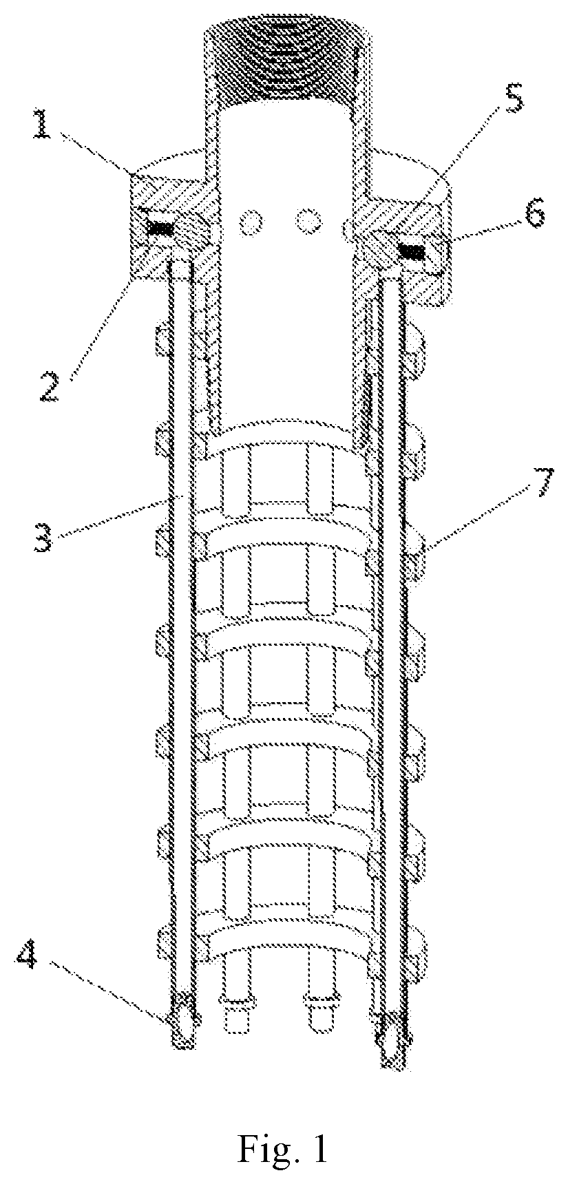
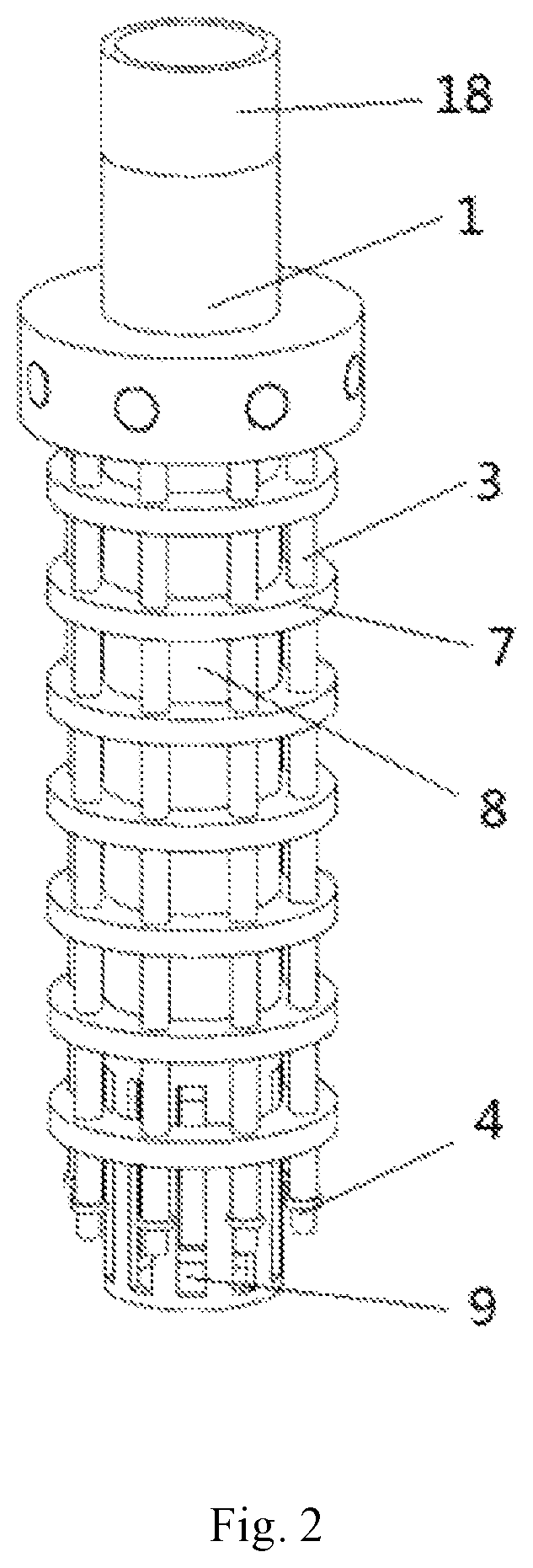
[0027]As shown in FIG. 1, an automatic cleaning device for suction port of electric submersible pump includes a pipe string joint (1), return springs (2), a connecting pipe (3), a nozzle (4), steel balls (5), sealing plugs (6) and retaining rings (7).

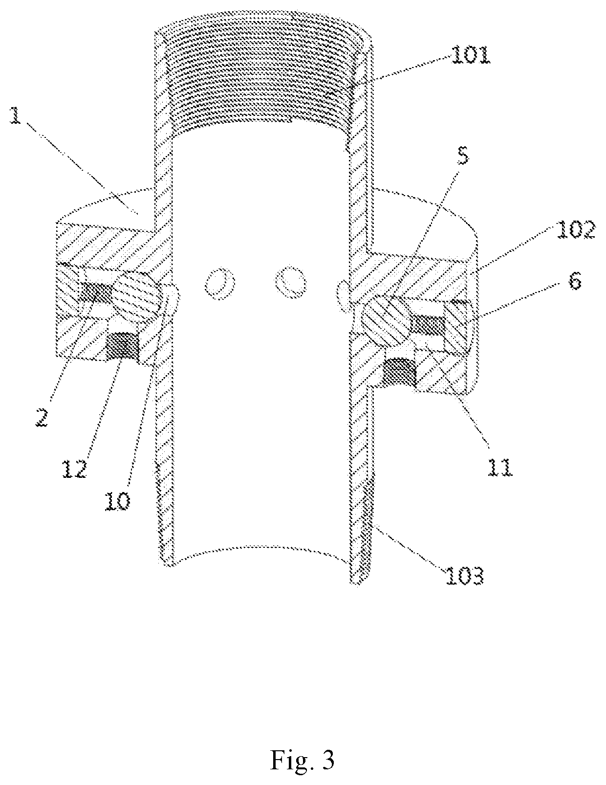
[0028]As shown in FIG. 1, FIG. 2 and FIG. 3, the pipe string joint (1) is a hollow cylinder, which includes a female thread (101) at an upper end, a boss (102) in a middle part, and a male thread (103) at a lower end. The upper end of the pipe string joint (1) is connected with an oil pipe (18) by threads, while the lower end is connected with the outlet of the electric submersible pump (8) by threads. A plurality of oil drain passage inlets (10), the steel balls (5), the return springs (2), the sealing plugs (6) a...


PUM


Abstract

The present invention relates to an automatic cleaning device for suction port of electric submersible pump. The pipe string joint is connected between the oil pipe and the electric submersible pump. A plurality of oil drain passage inlets, steel balls, return springs, sealing plugs and oil drain passage outlets are evenly distributed in circumferential direction of a boss. The upper end of the connecting pipe is connected with the outlet of the oil drain passage, and the lower end is connected with the nozzle. The retaining ring secures the connecting pipe on the housing of the electric submersible pump. A high-pressure fluid ejected from the nozzle directly acts on the suction port of the electric submersible pump. The present invention can automatically clean the suction port of the electric submersible pump by relying on the pressure difference between the outlet and the suction port of the electric submersible pump.

Description

BACKGROUND OF THE INVENTIONField of the Invention[0001]The present invention relates to the field of downhole tools for petroleum and natural gas production, in particular to an automatic cleaning device for suction port of electric submersible pump.Description of Related Art[0002]As a highly efficient and economical mechanical oil production equipment, an electric submersible pump has characteristics of large displacement, large lift range, large production pressure difference, strong adaptability and remarkable economic benefits. With the development of electric submersible pump technology, the electric submersible pump is widely used for oil production on offshore platforms. With the increasing difficulty of oil production on offshore platforms, higher requirements are raised for the suction and pumping performance of electric submersible pump. Especially for the development of heavy oil reservoirs, the viscosity of heavy oil is between 50 Pas and 300 Pas, and the asphaltine and ...

Claims


Application Information

Patent Timeline
Patent Type & Authority Patents(United States)
IPC IPC(8): F04D13/08E21B37/00F04D29/70
CPCF04D29/708E21B37/00F04D13/08F05D2250/51E21B37/08E21B41/0078
Inventor GOU, RUYICHEN, WEIYUZHAO, LIQIANGLIU, PINGLILUO, ZHIFENGDU, JUAN
Owner SOUTHWEST PETROLEUM UNIV
Why Eureka
Try Eureka