Sensing arrangement for stabilizing an offshore wind turbine installation arrangement

a technology for sensing arrangement and installation arrangement, which is applied in the direction of hydroelectric engineering, wind energy generation, foundation engineering, etc., can solve the problems of complex process, unwieldy components, and easy damage,

Active Publication Date: 2021-12-14
SIEMENS GAMESA RENEWABLE ENERGY AS
View PDF29 Cites 3 Cited by
  • Summary
  • Abstract
  • Description
  • Claims
  • Application Information

AI Technical Summary

Benefits of technology

[0010]Particularly when a hoisted component is to be mounted to the already partially assembled wind turbine, the inventive installation arrangement allows an advantageously precise and controlled guiding of the heavy load towards its target, for example the root end of a rotor blade can be guided very precisely to the corresponding pitch ring of the hub, even if the floating installation vessel is exhibiting significant movement in one or more directions and transferring these movements to the suspended load.
[0011]Equally, the inventive installation arrangement can be used when such a wind turbine component is to be detached from a wind turbine assembly and lowered to a floating installation vessel, and can greatly simplify the procedure by controlling elements of the lifting assembly on the basis of the sensed installation vessel motion.
[0013]An advantage of the inventive method is that the duration of a component lifting manoeuvre can be significantly reduced, since the inventive method is not sensitive to poor weather conditions and / or high seas. Any motion of the floating installation vessel caused by stormy conditions or rough seas can be detected by the sensor arrangement and taken into account by the controller, so that the position of the suspended load relative to the wind turbine assembly can be adjusted as required. The inventive method is not only faster than the known procedures, it is also significantly safer, since the load can always be moved in a controlled manner even in unfavourable conditions.
[0015]The controller of the inventive installation arrangement is therefore able to respond essentially immediately to any motion of the floating installation vessel, and to adjust the position of the suspended load accordingly. In this way, the load can advantageously always be moved in a very precisely controlled manner relative to the wind turbine assembly.
[0021]The load being lifted into place may be suspended from a hook on a cable or rope. The hook can be lowered or raised by adjusting the length of the cable or rope using an appropriate winch motor, for example a winch motor arranged on the crane's jib portion. The suspended load may oscillate, and the amplitude and direction of oscillation will depend to some extent on the wind conditions. To stabilise the load, one or more taglines are generally connected between the boom and the load so that any unwanted swinging motion of the load can be suppressed.
[0024]As indicated above, a load such as a rotor blade can be affected by the wind during the lifting manoeuvre. Uplift experienced by a very long rotor blade—for example with a length of 80 m or more—can make it difficult to precisely manoeuvre the horizontal blade into place for connecting to a pitch ring on the hub. Therefore, in a preferred embodiment of the invention, the lifting tool can comprise two or more actuators to effect an angular displacement of the load to counteract any uplift experienced by the suspended load during the lifting manoeuvre. For example, such actuators can be part of a lifting yoke, and can be realised as a number of hydraulic cylinders. In this way, the yoke of a lifting tool can be controlled to alter the angle of the suspended load about one or two horizontal axes.

Problems solved by technology

The procedure can be complicated by several factors.
However, not only are some of the components unwieldy and also vulnerable to damage (for example a rotor blade), the connection of one component to the already partially installed wind turbine can be made difficult by high winds, by any inherent instability of the jackup vessel, and by motion of the already partially installed wind turbine.
It can be very difficult to align the suspended load to its target for example to align the root end of a suspended rotor blade to a pitch ring on the spinner or hub—when the load is buffeted by the wind, and the target is also oscillating due to wind or water current loading.
These problems are exacerbated even further when the installation site is in relatively deep water.
However, when the installation site is further offshore and in deeper waters (60 m or more), the soil conditions may be such that the legs of the jackup vessel cannot penetrate to a sufficient depth.
If the legs of the jackup vessel are not designed for such water depths, over-extending them to reach and penetrate the seabed may result in an unstable setup.
Furthermore, the tower of a wind turbine in such a remote offshore wind park may reach a height of over 100 m, maybe even exceeding 140 m. This poses a further problem, since any crane used to lift components into place must be able to extend beyond this height, adding to the overall instability of the system.
The combination of deep water, poor soil conditions, and unstable jackup vessel can significantly prolong the installation procedure, thereby adding to the overall cost of construction of a wind park.
Any maintenance step that involves replacement of a rotor blade or generator will also require the use of such a jackup vessel and crane and will suffer from the same problems.
The erratic motion of the floating vessel in any combination of these six degrees of freedom makes it essentially impossible to predict the behaviour of a suspended load.
However, floating installation vessels have not been used in deep water for the assembly of offshore wind turbines owing to the difficulties arising from the many degrees of freedom of such a floating vessel.
The lifting assembly can hoist such a heavy and cumbersome wind turbine component from the floating installation vessel to the wind turbine assembly during a wind turbine installation procedure or during a maintenance procedure.
While the floating vessel can be equipped with a suitable propulsion arrangement to compensate for any translatory surge (fore and back) and sway (sideways) motions, there is no practicable way of preventing the translatory heave motion (up and down) that arises because of ocean swell or deep water waves.
It is also not practicable to suppress the rotatory motion of the floating installation vessel about its three axes, but rotation about any one of these axes will result in an oscillation of the suspended load.
Similarly, a pitching movement of the floating installation vessel will be transferred to the crane and will result in a swinging motion of the load.
When a wind turbine component such as a rotor blade or hub is being lifted into position to connect it to the already installed wind turbine assembly, the procedure is made more difficult by the swaying or oscillating motion of the tower and nacelle.
Uplift experienced by a very long rotor blade—for example with a length of 80 m or more—can make it difficult to precisely manoeuvre the horizontal blade into place for connecting to a pitch ring on the hub.

Method used


Image

  • Sensing arrangement for stabilizing an offshore wind turbine installation arrangement
  • Sensing arrangement for stabilizing an offshore wind turbine installation arrangement
  • Sensing arrangement for stabilizing an offshore wind turbine installation arrangement

Examples


Embodiment Construction

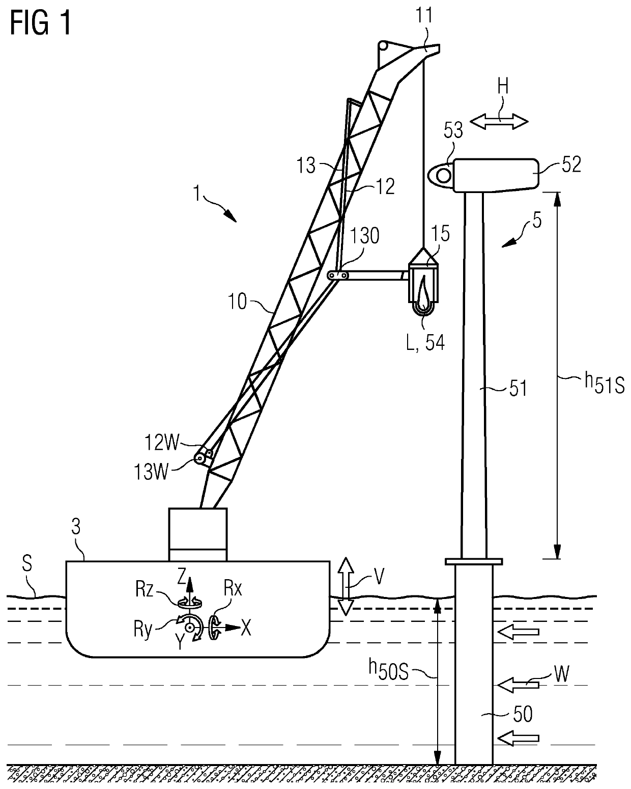
[0036]FIG. 1 shows elements of a know art installation arrangement 1, 3 during the installation of an offshore wind turbine 5. The diagram shows a floating installation vessel 3 beside the installation site. An offshore wind turbine 5 is being assembled on top of a supporting structure 50. The tower 51, nacelle 52 and hub 53 have already been assembled, and a load L in this case a rotor blade 54—is being hoisted towards a target. Here, the target is the hub 53, and the rotor blade 54 is to be connected to a blade pitch ring. Unlike a jackup vessel, which can be “anchored” to the ground by extending its legs to penetrate into the seabed to a sufficient depth, a floating installation vessel 3 cannot be prevented from moving. With respect to a three-dimensional coordinate system indicated in the diagram, the floating installation vessel 3 can exhibit rotatory motion about any of three axes X, Y, Z and can also exhibit translatory motion along any of the three axes X, Y, Z. While transl...


PUM


Abstract

Provided is an offshore wind turbine installation arrangement, including a lifting assembly realized to hoist a suspended load between a floating installation vessel and a wind turbine assembly, the lifting assembly including a crane supported by the floating installation vessel; a sensor arrangement realized to sense at least a motion of the floating installation vessel; and a controller realized to control elements of the lifting assembly on the basis of the sensed installation vessel motion to adjust the position of the suspended load relative to the wind turbine assembly. Also provided is a method of hoisting a load between a floating installation vessel and an offshore wind turbine assembly.

Description

CROSS-REFERENCE TO RELATED APPLICATIONS[0001]This application claims priority to PCT Application No. PCT / EP2018 / 063939, having a filing date of May 28, 2018, which is based on German Application No. 10 2017 209 876.7, having a filing date of Jun. 12, 2017, the entire contents both of which are hereby incorporated by reference.FIELD OF TECHNOLOGY[0002]The following describes an offshore wind turbine installation arrangement; and a method of hoisting a load between a floating installation vessel and an offshore wind turbine assembly.BACKGROUND[0003]To construct an offshore installation such as a wind turbine, it is usual to transport the relevant components to the installation site using a jackup vessel, and to use the jackup vessel as a relatively stable base from which to operate a crane to hoist the heavy components into place. For example, a jackup vessel can transport tower sections, nacelle, generator, rotor blades etc. to the installation site. In a series of lifting manoeuvres...

Claims


Application Information

Patent Timeline
Patent Type & Authority Patents(United States)
IPC IPC(8): B66C13/46B66C13/08F03D13/25B66C23/52F03D13/10
CPCB66C13/46B66C13/085B66C23/52F03D13/25F03D13/10B66C1/108B66C13/02B66C23/185Y02E10/727Y02E10/72E02D27/425E02B2017/0091E02B2017/0065E02B2017/0043
Inventor MOELLER, JESPER
Owner SIEMENS GAMESA RENEWABLE ENERGY AS
Why Eureka
Try Eureka