Internal-combustion engine and drive system

a drive system and internal combustion engine technology, applied in the direction of machine/engine, valve drive, vehicle sub-unit features, etc., can solve the problems of engine output deterioration, inferiority of four-cycle internal combustion engines to internal combustion engines of cycles, etc., to achieve improved thermal efficiency, reduce the effect of pumping loss and increased outpu

Active Publication Date: 2022-01-18
SAWADA FUKUEI +1
View PDF18 Cites 0 Cited by
  • Summary
  • Abstract
  • Description
  • Claims
  • Application Information

AI Technical Summary

Benefits of technology

[0024]According to the present invention, an intake stroke→a compression stroke→a combustion stroke→an exhaust stroke in a four-cycle internal-combustion engine are combined with an intake and compression stroke→a combustion and exhaust stroke in a two-cycle internal-combustion engine, so that the pumping loss is reduced, the output is increased, and thermal efficiency is improved, and this is suitable for an internal-combustion engine such as a gasoline engine of an automobile.

Problems solved by technology

As described above, in a conventional six-cycle internal-combustion engine, six-cycle strokes are set by adding an intake stroke and an exhaust stroke after four-cycle strokes, however, a pumping loss that occurs in these two-cycle strokes (intake and exhaust loss: an energy loss that occurs in the intake stroke and the exhaust stroke) causes engine output deterioration, and serves as a major cause of the six-cycle internal-combustion engines being inferior to four-cycle internal-combustion engines.

Method used


Image

  • Internal-combustion engine and drive system
  • Internal-combustion engine and drive system
  • Internal-combustion engine and drive system

Examples


example 1

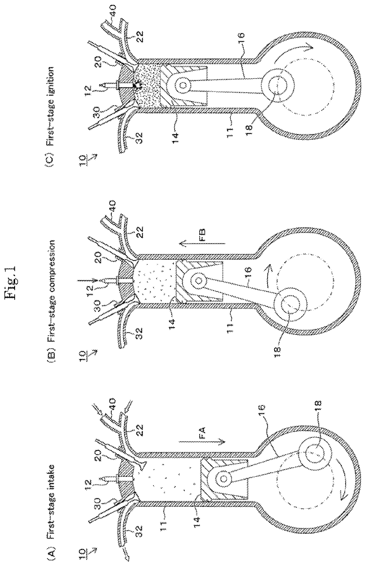
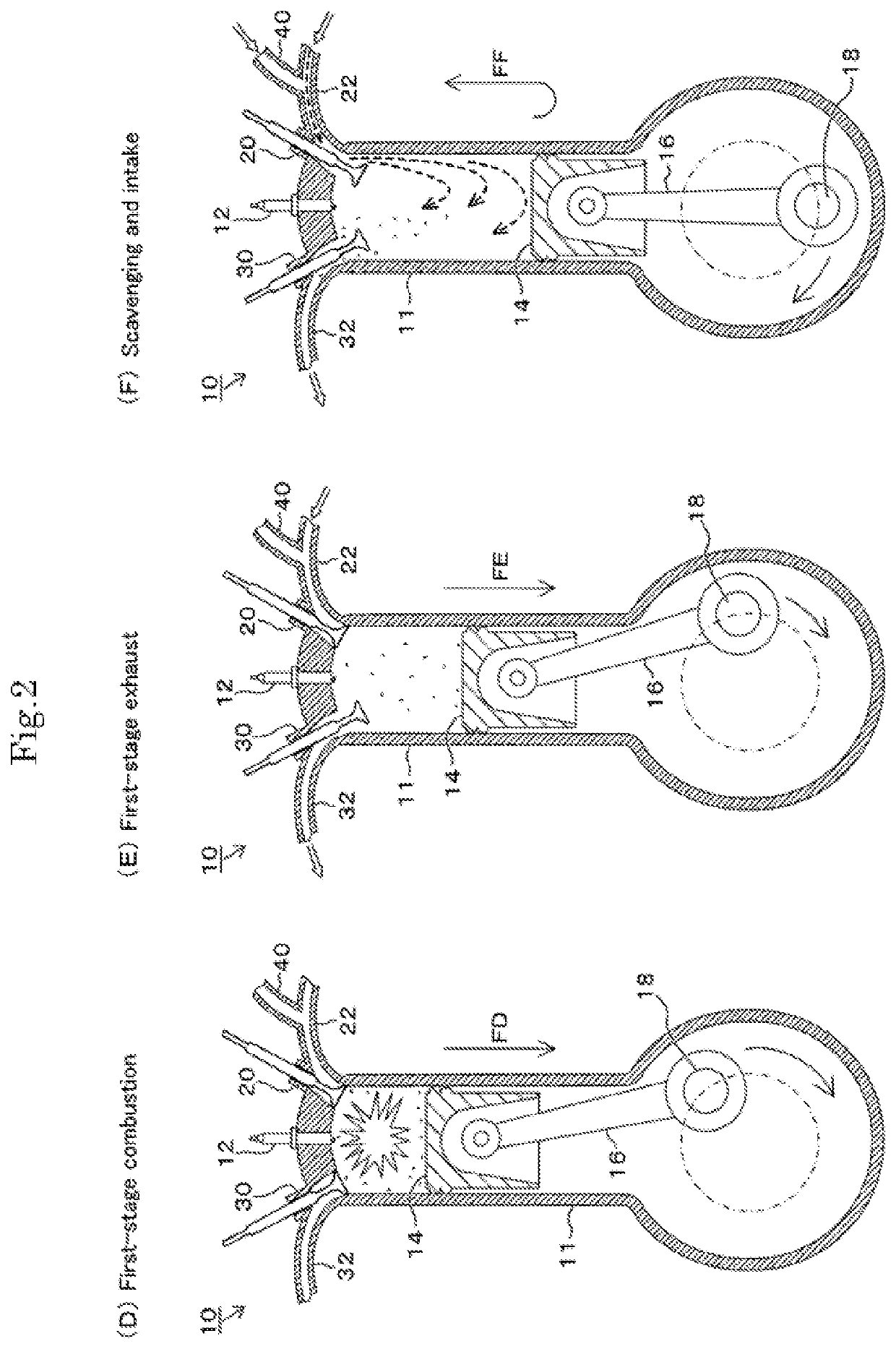
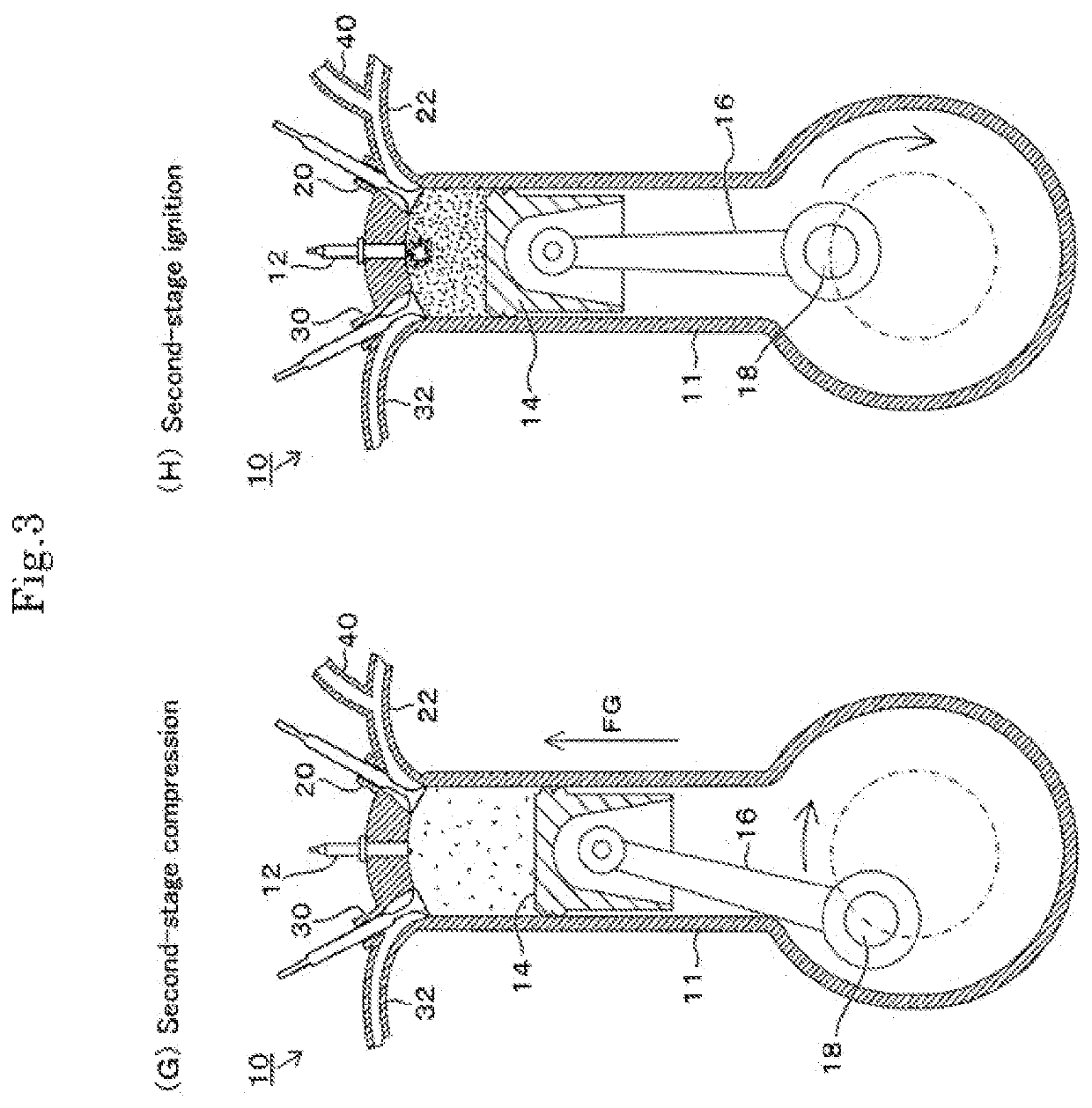
[0039]First, with reference to FIG. 1 to FIG. 6, Example 1 of six-cycle operation strokes of the present invention is described. As shown in FIG. 1(A), in a six-cycle engine 10 of the present example, for a cylinder 11, an ignition plug 12 and two valves 20 and 30 are provided, respectively. Of the valves 20 and 30, the intake valve 20 is a valve that opens when taking outside air into the cylinder 11, and compressed air by an external supercharger and recirculated exhaust gas by an EGR device are also suctioned into the cylinder 11 (refer to Example 2 described later). The exhaust valve 30 on the other hand is a valve that opens when gas after combustion is exhausted from the cylinder 11. To the intake valve 20, an intake port 22 for introducing outside air and a fuel port 40 for introducing fuel are connected, and to the exhaust valve 30, an exhaust port 32 for exhausting residual gas after combustion is connected. A piston 14 inside the cylinder 11 is joined to a crankshaft 18 vi...

example 2

[0059]Next, with reference to FIG. 7, Example 2 of the present invention is described. This example is an example of an engine system 100 constructed by providing an external supercharger and an EGR (Exhaust Gas Recirculation) device on the engine of Example 1 described above. As described above, the cylinder 11 of the six-cycle engine 10 is provided with two valves 20 and 30, and between the valves 20 and 30, an external supercharger (turbo-charger) 80 and an intercooler 90 are provided. In addition, an EGR device 200 is also provided, in which recirculated exhaust gases obtained from an exhaust side and an intake side of the external supercharger 80 described above are switched by a switching valve 210 and supplied to the intake valve 20 through an EGR cooler 220.

[0060]Next, as deleted description of the respective components, rocker arms 20A and 30A are provided on the valves 20 and 30, and are in contact with a cam of a camshaft. By rotation of this cam, opening and closing oper...

example 3

[0065]Next, with reference to FIG. 8 to FIG. 10, Example 3 of the present invention is described. To open and close the above-described valves 20 and 30 in accordance with the respective strokes shown in FIG. 1 to FIG. 4, the cam of the rocker arm is formed into a shape corresponding to opening and closing, and in this example, the shape of the cam is devised.

[0066]FIG. 8 show an example of a valve opening / closing mechanism suitable for the six-cycle engine of Example 1 described above. FIG. 9 are essential portion sectional views of the camshaft, and FIG. 10 show a relationship between the camshaft and opening and closing of the valves 20 and 30. (A) of each of these drawings shows a state at the time of low-speed rotation, and (B) of each of these drawings shows a state at the time of high-speed rotation.

[0067]In these drawings, the camshaft 300 is provided with a cam pulley 302, and a rotational drive force of a crankshaft timing gear 304 is transmitted through a timing belt 306....


PUM


Abstract

In an exemplary embodiment, an internal combustion engine, in which a valve is opened and closed when a piston reciprocates in a cylinder, has a configuration to perform repeatedly the following combined strokes: an intake stroke→a compression stroke→a combustion stroke→an exhaust stroke in a four-cycle internal combustion engine are combined with an intake and compression stroke→a combustion and exhaust stroke in a two-cycle internal combustion engine. The internal combustion engine can reduce pumping loss in a six-cycle internal combustion engine and increase the output.

Description

CROSS-REFERENCE TO RELATED APPLICATIONS[0001]This application is the U.S. National Phase under 35 U.S.C. § 371 of International Application PCT / JP2018 / 017279, filed Apr. 27, 2018, which claims priority to Japanese Patent Application No. JP2017-090654, filed Apr. 28, 2017. The International Application was published under PCT Article 21(2) in a language other than English.TECHNICAL FIELD[0002]The present invention relates to an improvement in an internal-combustion engine and a drive system suitable for an automobile engine, etc.BACKGROUND ART[0003]As automobile engines, two-cycle and four-cycle internal-combustion engines are known. A two-cycle internal-combustion engine causes one explosion per one rotation of a crankshaft, and a four-cycle internal-combustion engine causes one explosion per two rotations. On the other hand, a six-stroke cycle engine in which a scavenging and intake stroke and a scavenging and exhaust stroke are added after the four-cycle strokes is also known, and...

Claims


Application Information

Patent Timeline
Patent Type & Authority Patents(United States)
IPC IPC(8): F02B75/02F02M26/04F02M26/22B60K6/24B60K6/26F01L1/04F01L13/00
CPCF02B75/021B60K6/24B60K6/26F01L1/04F01L13/00F02M26/04F02M26/22B60Y2200/92B60Y2300/437B60Y2400/435B60Y2400/60F02B2075/027F02M26/05F02M26/06F02M26/07Y02T10/30F01L1/185F01L1/024F01L1/053F01L2001/0535F01L1/08F01L2001/0473F01L13/0057F01L2013/105F01L2305/00F01L2013/101F01L2013/108F02B25/145F02D23/00F02D39/04F02D19/0649F02D19/0647Y02T10/12
Inventor SAWADA, FUKUEISATO, SHIGERU
Owner SAWADA FUKUEI
Why Eureka
Try Eureka