Heat dissipation module and electronic device

a technology of heat dissipation module and electronic device, which is applied in the safety devices of heat exchange apparatus, indirect heat exchangers, lighting and heating apparatus, etc. it can solve the problems of liquid being unable to boil, central processing unit producing a great deal of heat, and liquid being unable to unleash the maximum efficacy, etc., and achieves better heat dissipation effect.

Active Publication Date: 2022-01-25
WISTRON CORP
View PDF26 Cites 0 Cited by
  • Summary
  • Abstract
  • Description
  • Claims
  • Application Information

AI Technical Summary

Benefits of technology

[0005]The present invention provides a heat dissipation module with a better heat dissipation effect.
[0006]The present invention further provides an electronic device, which includes the heat dissipation module and has better efficiency and reliability.
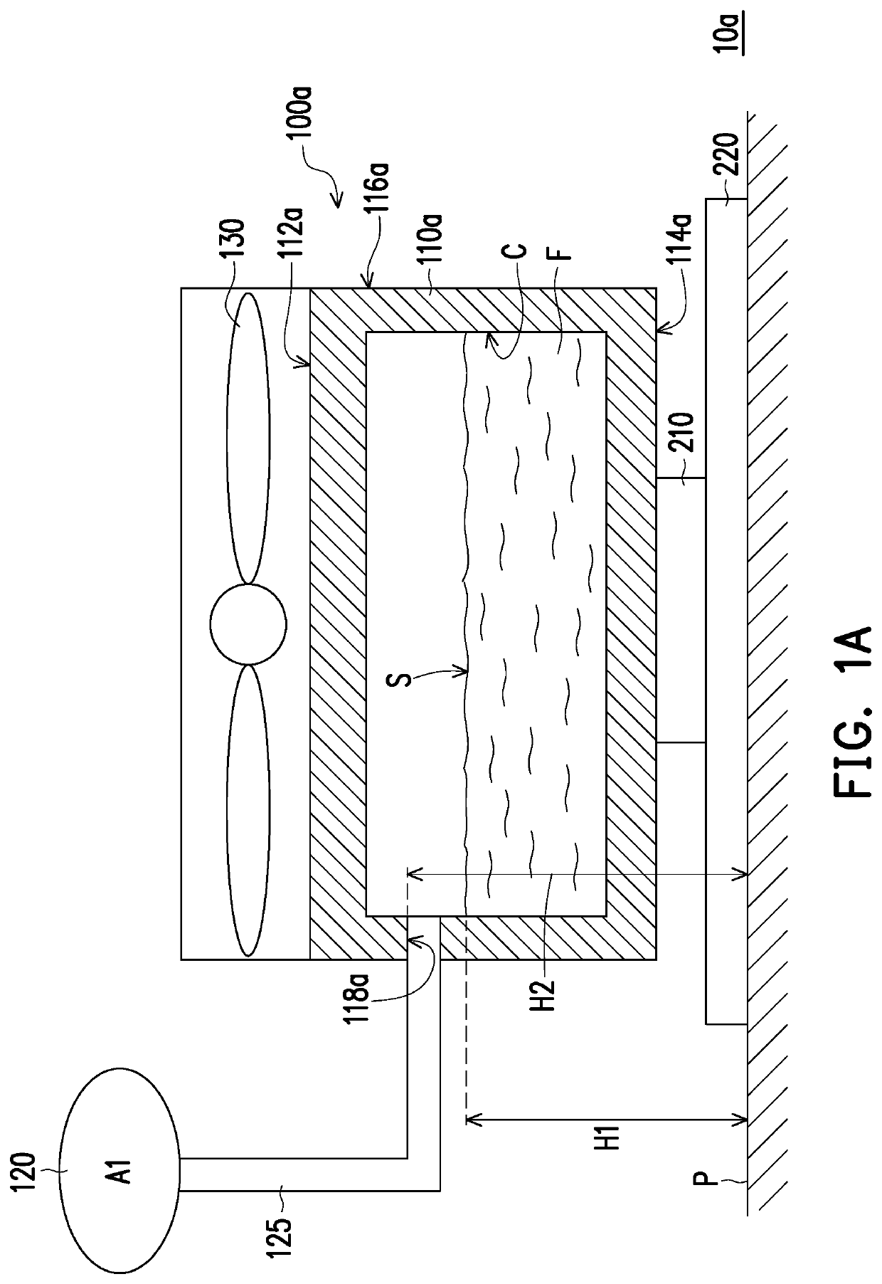
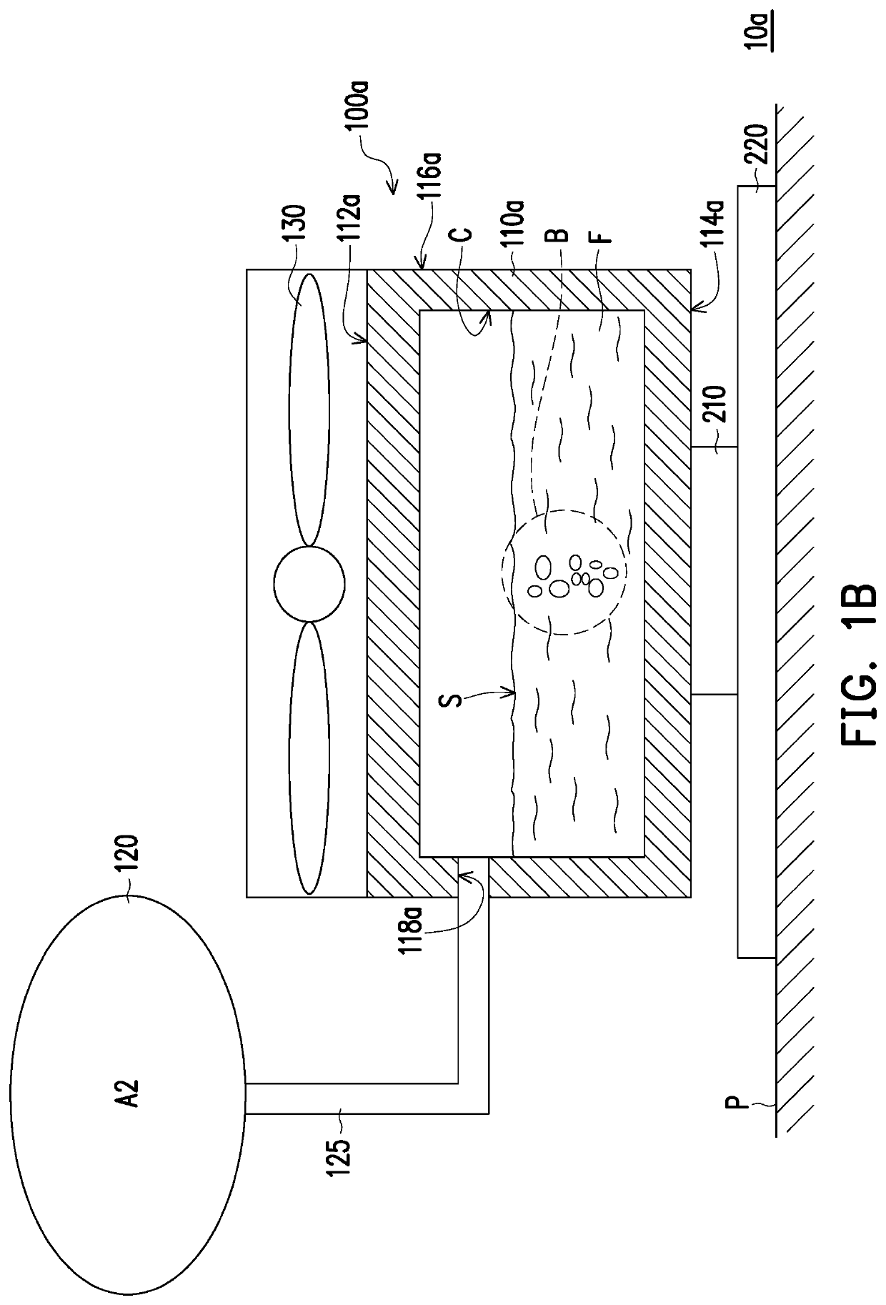
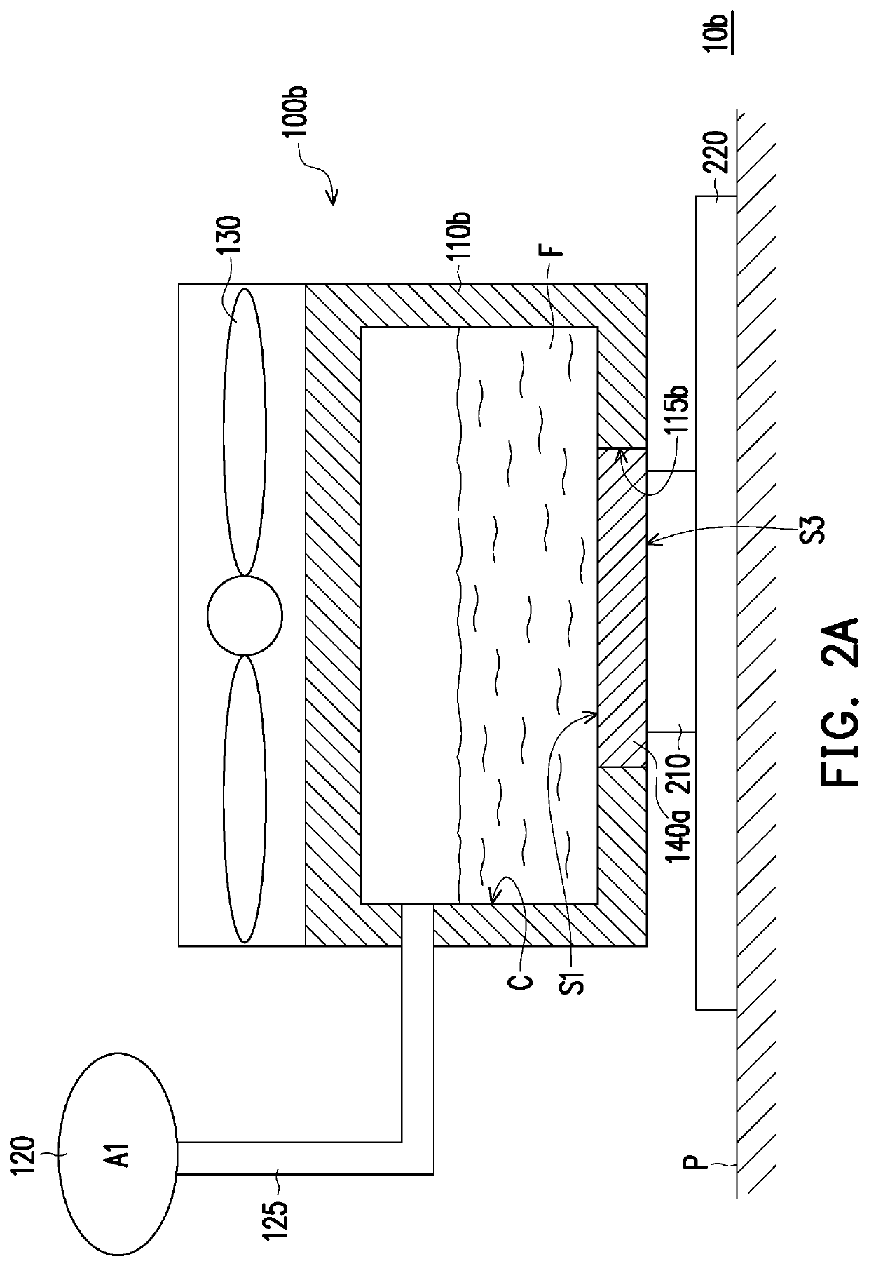
[0009]Based on the above, in the design of the heat dissipation module of the present invention, the buffer member is connected to the containing portion of the heat dissipation portion, and when the working fluid is heated, the buffer member is expanded to maintain a constant pressure within the containing portion. That is, the pressure in the containing portion is kept unchanged before and after the working fluid is heated. Thus, the problem of boiling point increasing of the working fluid as a result of drastic pressure change during vaporization can be mitigated, thereby increasing the heat dissipation efficiency of the heat dissipation module of the present invention. In addition, the electronic device which adopts the heat dissipation module of the present invention can have better efficiency and reliability as well.

Problems solved by technology

In the process of the turbo, the efficiency of the central processing unit will be greatly increased, as a result, the central processing unit will produce a great deal of heat within a short time, and if the temperature of the central processing unit cannot be effectively decreased, the central processing unit may be unable to unleash the maximum efficacy thereof.
However, under the condition that pressure increases, the boiling point of the liquid will increase rapidly, causing the liquid to be unable to boil, and as a result, the capability of heat dissipation will be decreased.
Therefore, the existing immersion type heat dissipation devices require a large space to solve the problem of pressure change, and consequently, a modularized immersion type heat dissipation device cannot be produced.

Method used


Image

  • Heat dissipation module and electronic device
  • Heat dissipation module and electronic device
  • Heat dissipation module and electronic device

Examples


Embodiment Construction

[0017]FIG. 1A is a schematic diagram of an electronic device according to an embodiment of the present invention. FIG. 1B is a schematic diagram of a buffer member expanding when a working fluid of a heat dissipation module in FIG. 1A is heated. Refer to both FIG. 1A and FIG. 1B, in the present embodiment, an electronic device 10a includes a heat dissipation module 100a, at least one heating component (only one heating component 210 is schematically depicted), and a mainboard 220. The heating component 210 is arranged on the mainboard 220 and the heat dissipation module 100a is arranged on the mainboard 220 and is in contact with the heating component 210. In addition, the heating component 210, for example, is a central processing unit or a graphic processing unit, but is not limited thereto.

[0018]Specifically, the heat dissipation module 100a of the present embodiment includes a heat dissipation portion 110a, a working fluid F, and a buffer member 120. The heat dissipation portion...


PUM

PropertyMeasurementUnit
boiling pointaaaaaaaaaa

Abstract

A heat dissipation module including a heat dissipation portion, a working fluid, and a buffer member is provided. The heat dissipation portion has a containing portion, the working fluid is contained in the containing portion, and the buffer member is connected to the containing portion. When the working fluid is heated, the buffer member is expanded to maintain a constant pressure within the containing portion.

Description

CROSS-REFERENCE TO RELATED APPLICATION[0001]This application claims the priority benefit of Taiwan application serial no. 108211231, filed on Aug. 23, 2019. The entirety of the above-mentioned patent application is hereby incorporated by reference herein and made a part of this specification.BACKGROUNDTechnical Field[0002]The present invention relates to a heat dissipation module and an electronic device, and in particular to a heat dissipation module with a buffer member and an electronic device adopting the heat dissipation module.Description of Related Art[0003]At present, the performance of central processing units (CPU) and graphic processing units (GPU) is more and more emphasized, and among them, Intel central processing units (Intel CPU) can be divided into two different types of turbos, i.e. a steady-state (PL1) turbo and a transient (PL2) turbo. In the process of the turbo, the efficiency of the central processing unit will be greatly increased, as a result, the central pr...

Claims


Application Information

Patent Timeline
Patent Type & Authority Patents(United States)
IPC IPC(8): H01L23/473F28F13/02H01L23/467F28F1/14F28F1/12F28F1/40
CPCH01L23/473F28F13/02H01L23/467F28F1/124F28F1/14F28F1/40F28F2245/02H01L23/427F28F13/182F28D15/0233F28D2021/0029F28F2265/12F28F2265/14
Inventor WU, HUAN-CHUN
Owner WISTRON CORP
Why Eureka
Try Eureka