Fuel pump with vapor purge valve assembly

a technology of vapor purge valve and fuel pump, which is applied in the field of fuel pumps, can solve the problems of increasing the time taken to build pressure, fuel vapor accumulation within the fuel pump, and particularly problematic accumulation, so as to achieve superior positioning of the vapor purge valve member, reduce the risk of vapor accumulation, and reduce the effect of vapor accumulation

Active Publication Date: 2022-02-01
DELPHI TECH IP LTD
View PDF15 Cites 0 Cited by
  • Summary
  • Abstract
  • Description
  • Claims
  • Application Information

AI Technical Summary

Benefits of technology

[0005]Briefly described, a fuel pump includes a housing which is tubular and extends from a housing inlet end to a housing outlet end; an inlet plate closing the housing inlet end of the housing, the inlet plate having an inlet passage which provides fluid communication into the housing; an end cap which closes the housing outlet end of the housing, the end cap having an outlet passage which provides fluid communication out of the housing and also having a vapor purge passage which selectively provides fluid communication out of the housing; an electric motor within the housing between the inlet plate and the end cap, the electric motor having a shaft which rotates about an axis; a pumping element rotationally coupled to the shaft such that rotation of the pumping element by the shaft causes fluid to be pumped from the inlet passage to the outlet passage and to be pressurized within the housing; and a vapor purge valve assembly. The vapor purge valve assembly includes a vapor purge valve member located within the vapor purge passage, the vapor purge valve member being moveable between 1) a first position which blocks fluid communication through the vapor purge passage and 2) a second position which provides fluid communication through the vapor purge passage; and a vapor purge valve retainer fixed to the end cap, the vapor purge valve retainer having a first leg, a second leg which is opposed to the first leg, and a cross-beam which joins the first leg and the second leg, wherein the vapor purge valve member is stopped by the cross-beam at the second position. The fuel pump with vapor purge valve assembly as disclosed herein provides simplicity and cost effectiveness in manufacture, minimizes flow restriction, provides superior positioning of a vapor purge valve member, prevents contamination due to debris from the manufacturing processes, and prevents siphoning when a jet pump is used with the fuel pump.

Problems solved by technology

It is known that when such fuel pumps are not operating, fuel vapor may accumulate within the fuel pump.
This accumulation of fuel vapor increases the time taken to build pressure when operation of the fuel pump is commenced.
So-called start-stop applications where the internal combustion engine of the motor vehicle is stopped to reduce idle time of the internal combustion engine, for example at stop lights, may be particularly problematic because the driver of the motor vehicle expects a quick restart of the internal combustion engine when commanded, and the restart can be delayed due to accumulation of fuel vapor.
One solution that has been used to purge fuel vapor is a fixed purge orifice which allows fuel vapor to be purged directly to the fuel tank, however, this known fixed purge orifice is parasitic since a small portion of the fuel pumped by the fuel pump is passed through the fixed purge orifice during its entire operating time, thereby reducing efficiency.
Furthermore, this known fixed purge orifice only purges fuel vapor from the pump section and not from areas closer to the outlet of the fuel pump, and consequently, does not address all fuel vapor that has accumulated.
In order to resolve the siphoning issue, it has been known to provide a check valve in the passage which supplies the jet pump, however, this adds components and reduces the efficiency of the jet pump.

Method used


Image

  • Fuel pump with vapor purge valve assembly
  • Fuel pump with vapor purge valve assembly
  • Fuel pump with vapor purge valve assembly

Examples


Embodiment Construction

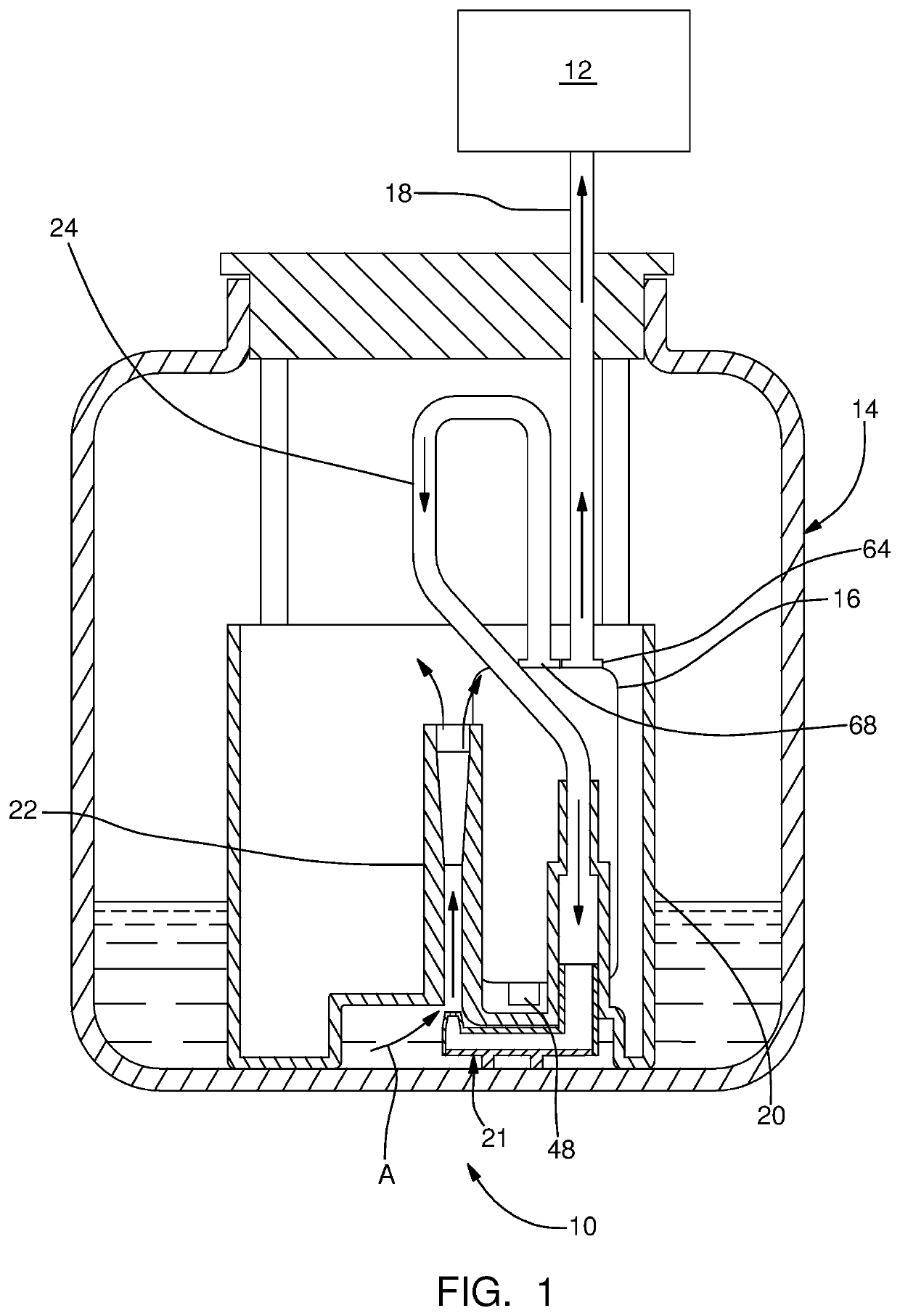
[0016]Referring initially to FIG. 1, a fuel system 10 is shown in accordance with the invention for supplying fuel to a fuel consuming device, illustrated by way of non-limiting example only, as an internal combustion engine 12. The fuel of fuel system 10 may be any liquid fuel customarily used, for example only, gasoline, diesel fuel, alcohol, ethanol, and the like, and blends thereof.

[0017]Fuel system 10 includes a fuel tank 14 for storing a quantity of fuel and a fuel pump 16 for pumping fuel from fuel tank 14 to internal combustion engine 12. Fuel that is pumped by fuel pump 16 is communicated to internal combustion engine 12 through a fuel supply line 18. Fuel pump 16 is an electric fuel pump which will be described in greater detail later. Fuel pump 16 is disposed within a fuel reservoir 20 which is a separate container within fuel tank 14 that is filled with fuel from fuel tank 14. When the fuel level in fuel tank 14 is sufficiently high, fuel reservoir 20 is filled by fuel s...


PUM


Abstract

A fuel pump includes a housing which is tubular; an inlet plate closes one end of the housing and an end cap closes the other end of the housing. The end cap includes an outlet passage and a vapor purge passage. An electric motor within the housing rotates a pumping element to pump fuel through the fuel pump. A valve assembly of the fuel pump includes a valve member located within the purge passage, the valve member being moveable between a first position which blocks fluid communication therethrough and a second position which provides fluid communication therethrough. A valve retainer fixed to the end cap includes a first leg, a second leg which is opposed to the first leg, and a cross-beam which joins the first leg and the second leg. The valve member is stopped by the cross-beam at the second position.

Description

TECHNICAL FIELD OF INVENTION[0001]The present invention relates to a fuel pump; more particularly to a fuel pump with a vapor purge valve assembly which allows fuel vapor to be purged from the fuel pump.BACKGROUND OF INVENTION[0002]Fuel pumps for pumping fuel, for example, from a fuel tank of a motor vehicle to an internal combustion engine of the motor vehicle, are known. U.S. Pat. No. 6,824,361 to Yu et al. shows a typical electric fuel pump which includes an impeller located axially between stationary inlet and outlet plates. It is known that when such fuel pumps are not operating, fuel vapor may accumulate within the fuel pump. This accumulation of fuel vapor increases the time taken to build pressure when operation of the fuel pump is commenced. So-called start-stop applications where the internal combustion engine of the motor vehicle is stopped to reduce idle time of the internal combustion engine, for example at stop lights, may be particularly problematic because the driver...

Claims


Application Information

Patent Timeline
Patent Type & Authority Patents(United States)
IPC IPC(8): F02M37/20F02M55/00F02M37/08F04D9/00F16K24/04F04B53/06
CPCF02M55/007F02M37/08F02M37/20F04D9/006F04B53/06F16K24/046F02M37/106
Inventor CARRILLO, CONRADOSCHIAFFINO, VICTOR A.LARA, CARLA P.MORENO, ALEJANDRO
Owner DELPHI TECH IP LTD
Why Eureka
Try Eureka