
3-dimensional block type bone graft

a bone graft and three-dimensional technology, applied in bone implants, prostheses, medical science, etc., can solve the problems of large loss of bone grafts, immune rejection and slow bone formation, and hardly provide the required amount of bone tissues, etc., to achieve fast blood circulation, perform more simply and conveniently, and excellent porosity

Active Publication Date: 2022-02-08
EK
View PDF1 Cites 0 Cited by
  • Summary
  • Abstract
  • Description
  • Claims
  • Application Information

AI Technical Summary

Benefits of technology

The present invention provides a 3-dimensional block type bone graft that is not spilled out, making the grafting process simpler and more convenient. The graft has excellent porosity, allowing fast blood circulation and providing space for bones to grow and effectively perform bone formation through osteoinduction and osteoconduction. The bone graft can be broken down to small pieces and rearranged into a new form as necessary, to maintain volume and seal the grafting site.

Problems solved by technology

Although the autografting does not have the concern of infection or immune rejection, the autografting requires a secondary surgery and may hardly provide a required amount of bone tissues.
In addition, the allografting has the concern of immune rejection and secondary infection, and the xenografting has problems of immune rejection and slow bone formation.
However, since a conventional bone graft formed of the calcium phosphate compounds is mainly provided as powder, the conventional bone graft has limitations in that the bone graft may be spilled from a bone defect during the grafting, causing a large loss of the bone graft and making it difficult to perform the grafting while requiring a long time, and the bone graft has insufficient porosity so that slow blood absorption into the bone graft may occur and an effective space for allowing a bone to grow therein may be insufficient, resulting in ineffective bone formation.

Method used


Image

  • 3-dimensional block type bone graft
  • 3-dimensional block type bone graft
  • 3-dimensional block type bone graft

Examples


Embodiment Construction

[0019]Hereinafter, a 3-dimensional block type bone graft according to embodiments of the present invention will be described in detail with reference to the accompanying drawings.

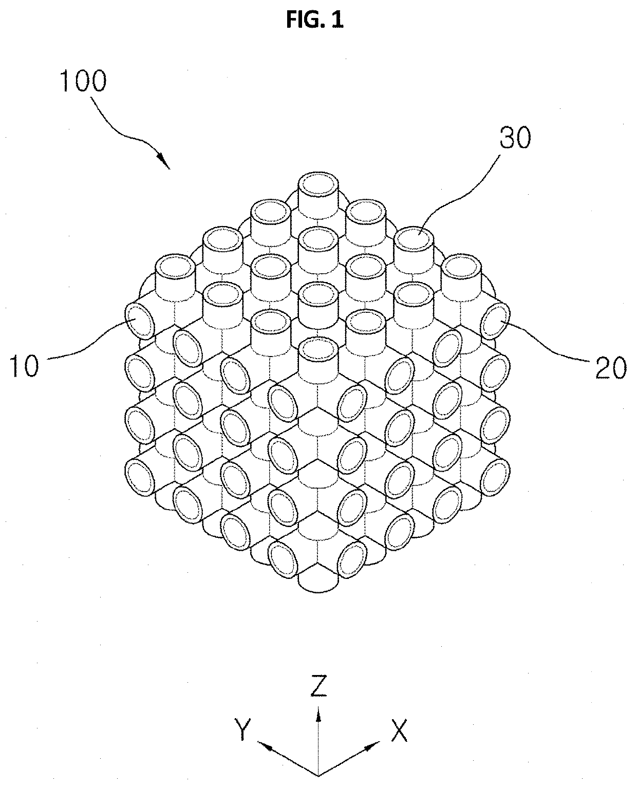
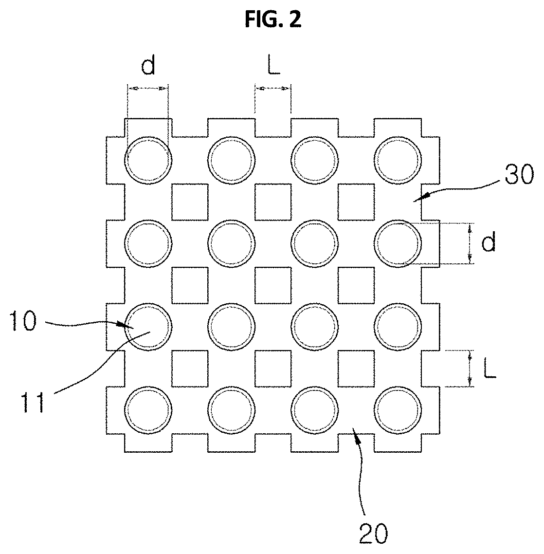
[0020]As illustrated in FIGS. 1 and 2, a 3-dimensional block type bone graft 100 according to the present invention includes a plurality of first channels 10, second channels 20, and third channels 30, which are configured in a 3-dimensional shape.

[0021]The bone graft 100 according to the present invention is formed of a mixture of hydroxyapatite (HA) and β-tricalcium phosphates (β-TCP), and a mixing ratio of HA and β-TCP is preferably 6:4.

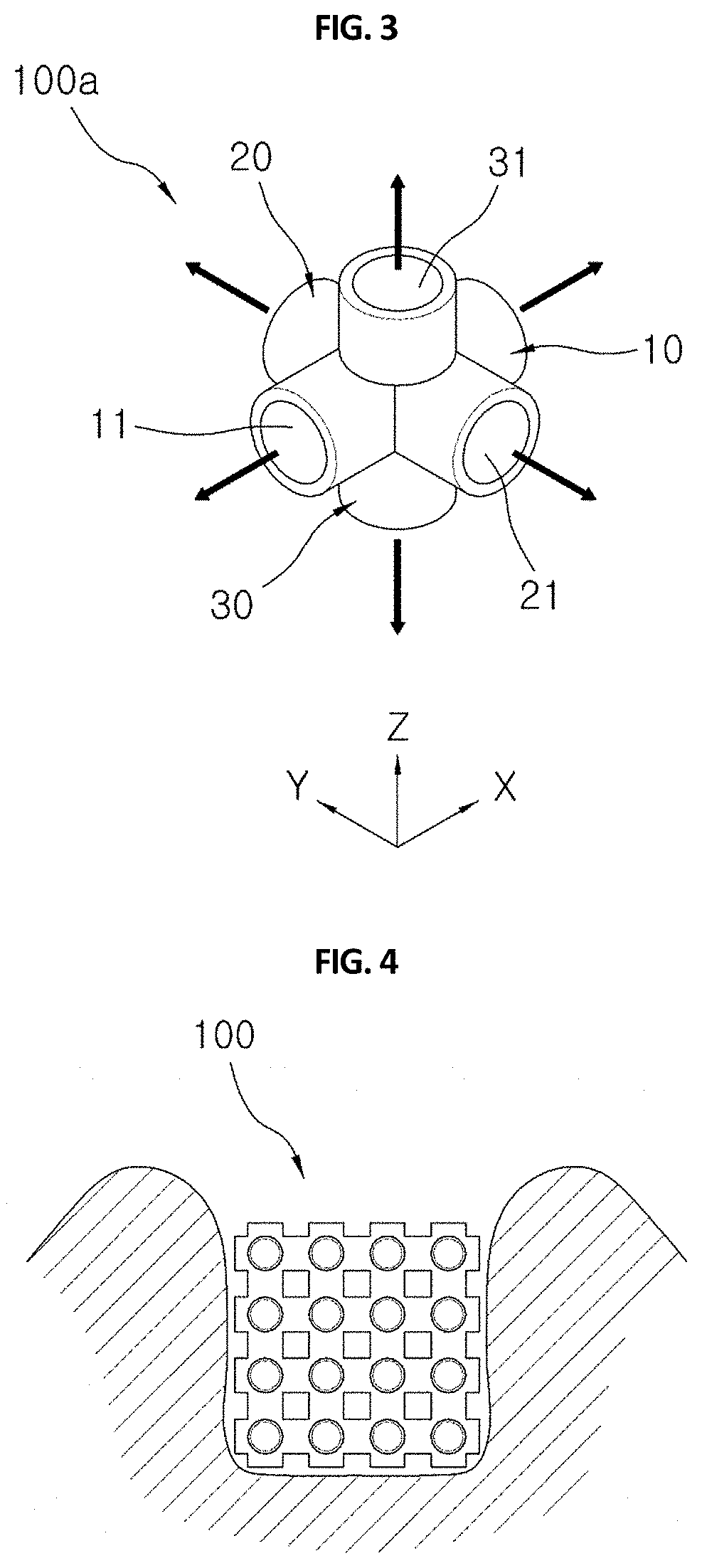
[0022]The channels included in the present invention denote tubes having a hollow passage to allow blood to be circulated through an inside of the tube, and the first channels 10, the second channels 20, and the third channels 30 are distinguished from each other according to extension directions thereof.

[0023]In other words, the first channel 10 is a channel formed there...


PUM


Abstract

A 3-dimensional block type bone graft includes a plurality of first channels extending horizontally in forward and backward directions and arranged at a predetermined interval in left and right directions and upward and downward directions, a plurality of second channels extending horizontally in the left and right directions and arranged at a predetermined interval in the forward and backward directions and the upward and downward directions, and a plurality of third channels extending vertically in the upward and downward directions and arranged at a predetermined interval in the forward and backward directions and the left and right directions, wherein the first channels, the second channels, and the third channels intersect perpendicularly to each other to communicate with each other so that the first channels, the second channels, and the third channels are configured in a 3-dimensional shape.

Description

CROSS-REFERENCE TO RELATED APPLICATION AND CLAIM OF PRIORITY[0001]This application is a Continuation-In-Part of co-pending application Ser. No. 14 / 556,006 filed on Nov. 28, 2014, the entire contents of all are hereby incorporated by reference.BACKGROUND1. Field of the Invention[0002]The present invention relates to a bone graft used in a bone defect.2. Description of the Related Art[0003]Bone tissue is the only hard tissue in a living body, and a region where the bone tissue is damaged is filled with a bone to create a new bone. Methods for recovery of such bone defects include autografting, allografting, and xenografting.[0004]Although the autografting does not have the concern of infection or immune rejection, the autografting requires a secondary surgery and may hardly provide a required amount of bone tissues. In addition, the allografting has the concern of immune rejection and secondary infection, and the xenografting has problems of immune rejection and slow bone formation.[0...

Claims


Application Information

Patent Timeline
Patent Type & Authority Patents(United States)
IPC IPC(8): A61F2/00A61F2/28A61F2/30
CPCA61F2/28A61F2002/2835A61F2002/3092A61F2002/30199A61F2002/30303A61F2002/30593
Inventor LEE, JAEJOON
Owner EK
Learn More