Method and apparatus for removable catheter visual light therapeutic system

a technology of visual light and therapeutic system, which is applied in the field of methods and equipment for removing catheter visual light therapeutic system, can solve the problems of detriment to the emr source and may need to be limited, and achieve the effect of stimulating healthy cell growth

Active Publication Date: 2022-02-08
LIGHT LINE MEDICAL INC
View PDF24 Cites 5 Cited by
  • Summary
  • Abstract
  • Description
  • Claims
  • Application Information

AI Technical Summary

Benefits of technology

[0017]The at least one coupling to connect the radiation source to the EMR conduction system may comprise at least one feature that allows for the coupling to be readily removable from the removable EMR conduction system. This coupling may be achieved by utilizing a uniquely designed connection, a pre-manufactured coupling system, or any combination thereof that optimizes the coupling efficiency and utility. Further, the coupling that couples the removably insertable EMR conduction system to the EMR source may comprise more than one coupling with an intermediate section optimized to further the propagation of the EMR. In one exemplary embodiment, the EMR source is coupled to a patch cable or EMR conduction extending segment, which is then coupled to the formal removably insertable EMR conduction system.
[0029]A further exemplary embodiment of the removable EMR conduction system comprises an optical element such as at least one LED, its associated wiring components, and a scaffold. The LED(s) may emit EMR based on the LED's inherent distribution, or may utilize another optical element, such as a lens or mirror, to focus or diffuse the EMR in the direction of interest. In addition, more than one LED could be arranged in an array to appropriately emit EMR for maximal therapeutic benefit. The LED(s), together with associated wiring components may be permanently or removably attached to the scaffold, which allows for removable insertion of the EMR conduction system into a catheter. The scaffold may be rigid, semi-rigid, malleable, elastic, or flexible, or any combination thereof.

Problems solved by technology

It is possible that the EMR source may generate heat, which could be detrimental to the EMR source and may need to be limited.

Method used


Image

  • Method and apparatus for removable catheter visual light therapeutic system
  • Method and apparatus for removable catheter visual light therapeutic system
  • Method and apparatus for removable catheter visual light therapeutic system

Examples


Embodiment Construction

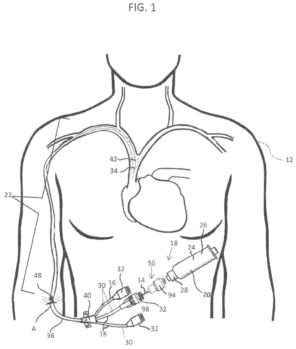
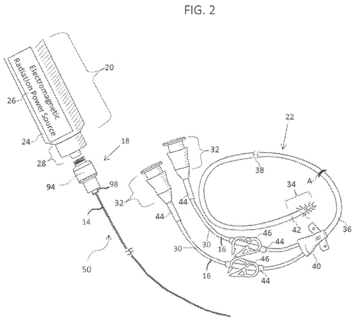
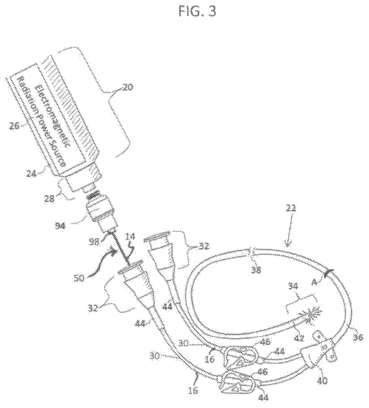
[0045]The exemplary embodiments of the present disclosure will be best understood by reference to the drawings, wherein like parts are designated by like numerals throughout. It should be understood that the components of the exemplary embodiments, as generally described and illustrated in the figures herein, could be arranged and designed in a wide variety of different configurations. Thus, the following more detailed description of the exemplary embodiments of the apparatus, system, and method of the present disclosure, as represented in FIGS. 1 through 11, is not intended to limit the scope of the invention, as claimed, but is merely representative of exemplary embodiments.

[0046]In this application, the phrases “connected to”, “coupled to”, and “in communication with” refer to any form of interaction between two or more entities, including mechanical, capillary, electrical, magnetic, electromagnetic, pneumatic, hydraulic, fluidic, and thermal interactions.

[0047]The phrases “attac...


PUM


Abstract

A medical device assembly is provided for removable insertion into a catheter with a lumen. The medical device assembly comprises an electromagnetic radiation (EMR) source for providing non-ultraviolet, therapeutic EMR having an intensity sufficient to inactivate one or more infectious agents and / or to stimulate healthy cell growth causing a healing effect, and a removable EMR conduction system at least partially insertable into and removable from the lumen of the catheter. The EMR conduction system has at least one optical element providing axial propagation of the therapeutic EMR through an insertable elongate body. The elongate body may have an exterior surface between a coupling end and a distal end tip that has at least one modified portion permitting the radial emission of therapeutic EMR from the elongate body proximate the modified portion. Such modified portion may be gradient along the exterior surface.

Description

RELATED APPLICATION[0001]This application is a continuation-in-part of U.S. patent application Ser. No. 15 / 424,732, filed on Feb. 3, 2017 and entitled METHODS AND APPARATUS FOR REMOVABLE CATHETER VISUAL LIGHT THERAPEUTIC SYSTEM and claims the benefit of U.S. Provisional Patent Application, Ser. No. 62 / 292,028 that was filed on Feb. 5, 2016, for an invention titled METHOD AND APPARATUS FOR REMOVABLE CATHETER VISUAL LIGHT STERILIZATION SYSTEM, each of which is incorporated herein by this reference, as if fully set forth herein.BACKGROUND OF THE INVENTIONField of the Invention[0002]The present invention is a method and apparatus to provide therapeutic doses of non-ultraviolet light to inactivate infectious agents residing on, within, or generally around a catheter while the catheter is residing within a body cavity and / or to stimulate healthy cell growth causing a healing effect. In particular, the disclosure is a medical device assembly that utilizes non-ultraviolet visual therapeutic...

Claims


Application Information

Patent Timeline
Patent Type & Authority Patents(United States)
IPC IPC(8): A61N5/06A61M25/01A61N5/067
CPCA61N5/0601A61M25/0108A61N5/062A61N5/0624A61N5/067A61N2005/063A61N2005/0629A61N2005/0651A61N2005/0662A61N2005/0602A61M39/105A61M39/10
Inventor LONG, CURTIS D.BARNECK, MITCHELL D.RHODES, NATHANIEL L.ALLEN, JAMES P.DE LA PRESA, MARTIN
Owner LIGHT LINE MEDICAL INC
Why Eureka
Try Eureka