Device for preheating a fluid, in particular coolant for a combustion engine

a technology for preheating fluids and combustion engines, which is applied in the direction of fluid heaters, electric heating, electrical apparatus, etc., can solve the problems of difficult placement on the circuit, low yield of heaters, and unreliable heaters in time, so as to reduce the loss in the atmosphere, increase heat exchange efficiency, and optimize thermal efficiency

Active Publication Date: 2022-02-08
VOLANTE NINO
View PDF12 Cites 0 Cited by
  • Summary
  • Abstract
  • Description
  • Claims
  • Application Information

AI Technical Summary

Benefits of technology

[0017]The invention aims to provide a fluid heating device which overcomes at least one of the above mentioned disadvantages. More particularly, the invention aims to provide a fluid heating device having improved thermal efficiency and being of simple and economical construction. More particularly, the invention aims to provide a compact fluid heating device with a simple and inexpensive construction.Technical Solution
[0041]The measures of the invention have the advantage of optimizing the thermal efficiency, specifically by increasing the efficiency of heat exchange between the at least one heating resistance and the fluid, and also by reducing losses in the atmosphere. Indeed, the construction of the heating body and the arrangement of the resistances according to the invention allows an intimate contact between the resistances and the fluid. The at least one heating resistance indeed extends along the major part of the fluid path as they are arranged in parallel along the main direction of the passageway. Dividing the passageway into several longitudinal channels increases the heat transfer for a given length of the passageway. Electric resistances can be supplied with 110, 230, 400 or 480 VAC (typically on the home network) during engine preheating while the vehicle is stationary. One or more additional resistances can be supplied with voltage 12 or 24 VDC by the vehicle battery to continue heating when the engine is running. The compact and geometric shape of the heating body makes it easy to isolate by equipping it with an insulating coat. The latter may be provided removable, which is made easy again by the optimized shape of the heating body. The heating body can be performed at low cost from a block of material such as aluminum with some conventional and controlled machining operations.

Problems solved by technology

To reduce its size, the specific load per cm2 is very high, which makes such heaters unreliable devices in time.
The yield thereof is very low and the placement on the circuit is not easy to allow for thermal movement.
For over ten years, engine manufacturers have significantly changed the design of the water chambers in engines and it becomes difficult to place this type of heater because this configuration does no longer render possible to create an effective flow through this thermosiphon principle and so to properly and uniformly heat the engines.
However, the size is still too high to allow easy placement on mid-sized vehicles (passenger cars, ambulances, trucks .
In addition, commonly used pumps must be positioned horizontally, which further reduces the possibilities of integration under the bonnet.
This would cause a boiling of the fluid at the heating element that would result in a degradation of the shield thereof, and then lead to a premature rupture of the element.
The thermal connection between the resistances and the fluid is, however, not optimal.
In addition, the main body is subject to significant losses to the atmosphere.
The thermal efficiency of this device is therefore not optimal.
This system seems to work on the principle of thermosiphon, which limits the heating performance.
This preheating device has the same disadvantage as that of the document cited above, namely that the thermal contact between the heating elements and the fluid is not optimized.
This system seems to work on the principle of thermosiphon, which limits the heating performance.
This direct contact is not desirable for some applications.
In addition, the overall size of the device is fairly large and may pose integration problems.
This system seems to work on the principle of thermosiphon, which limits the heating performance.
The power of heat exchange is limited in this teaching, especially because of the limited diameter of the curved pipe and the limited number of heating elements.
The heat exchange power is very limited.
Due to the remoteness of the electrical resistances vis-a-vis of the U-shaped channels, the heat exchange power is limited.
However, the thermal exchange takes place mainly in the middle of the path followed by the fluid and a risk of heat loss at the outlet location of the fluid is present.

Method used


Image

  • Device for preheating a fluid, in particular coolant for a combustion engine
  • Device for preheating a fluid, in particular coolant for a combustion engine

Examples


Embodiment Construction

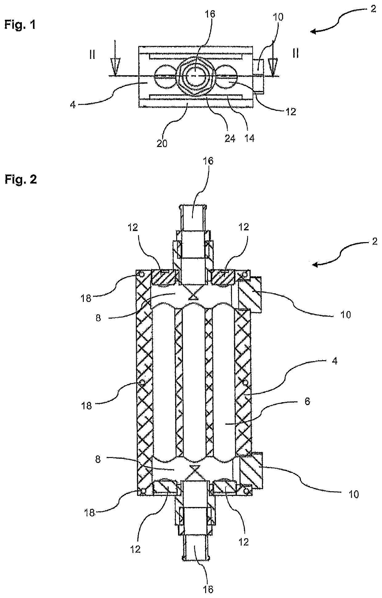
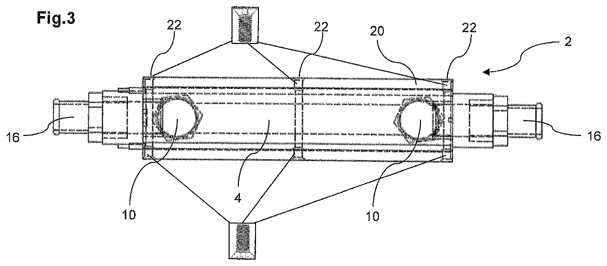
[0045]The fluid heating or preheating device shown in FIGS. 1 to 3 essentially comprises a solid member 4 of generally rectangular section having a through passageway for the fluid. The passageway comprises three straight and parallel channels 6 passing through the block from side to side. These channels are preferably produced by drilling.

[0046]The passageway also comprises two transverse channels 8, each being near one of the two ends of the longitudinal channels 6. These channels have the function to ensure a placing in communication of the longitudinal channels. These transverse channels are preferably made by drilling.

[0047]The heating body 4 can be made by extrusion with the longitudinal channels. The transverse channels can then be made by machining.

[0048]The longitudinal channels 6 open out on the front and back of the body 4. The areas of these faces where the lateral channels open are fitted with plugs 12, while the areas of said faces where the central channel opens are p...


PUM


Abstract

The invention relates to a device for heating a fluid (2), comprising a heating body (4) having a through passageway (6, 8) for the fluid and provided with at least one groove (14) on its outer surface; at least one electrical resistance (24) housed in the at least one groove (14) of the heating body. The device further comprises at least one closure plate (20) of the at least one groove (14) overlying the at least one resistance (24).

Description

TECHNICAL FIELD[0001]The invention relates to a device for heating a fluid, more particularly a coolant of an internal combustion engine. The present invention also relates to a fluid heating process for various applications.[0002]The fluids may be sanitary water, chlorinated water, water with glycol, hydrocarbons (diesel, gasoline, oil, . . . ), vegetable oils (colza), gases in liquid or gaseous state, . . . .[0003]Examples of heating applications are numerous: industrial, generators, cogeneration groups, combustion engines (petrol, diesel, LPG, . . . ), pools, spas, hot water, aquariums, ponds, . . . .PRIOR ART[0004]The engines of emergency generators (hospitals, enterprises, . . . ) must be maintained at a temperature (˜40° C.) that is ideal for a direct starting thereof, to ensure within a few second electricity supply in the event of mains failure.[0005]The engines of emergency vehicles (ambulances, fire brigade, . . . ) should also be heated beforehand to ensure an immediate s...

Claims


Application Information

Patent Timeline
Patent Type & Authority Patents(United States)
IPC IPC(8): F24H1/14F24H1/12H05B3/20
CPCF24H1/142F24H1/121H05B3/20H05B2203/02H05B2203/022H05B2214/03
Inventor CARLENS, JEAN-CLAUDEZUNE, JEAN-FRANÇOIS
Owner VOLANTE NINO
Why Eureka
Try Eureka