
Optical reader for analyte testing

an analyte and optical reader technology, applied in the field of analyte collection and testing systems and methods, can solve the problems of a significant amount of time for reporting results, and achieve the effect of optimal and reliable performance of our system and robust optical performan

Active Publication Date: 2022-03-01
EVANOSTICS LLC
View PDF109 Cites 0 Cited by
  • Summary
  • Abstract
  • Description
  • Claims
  • Application Information

AI Technical Summary

Benefits of technology

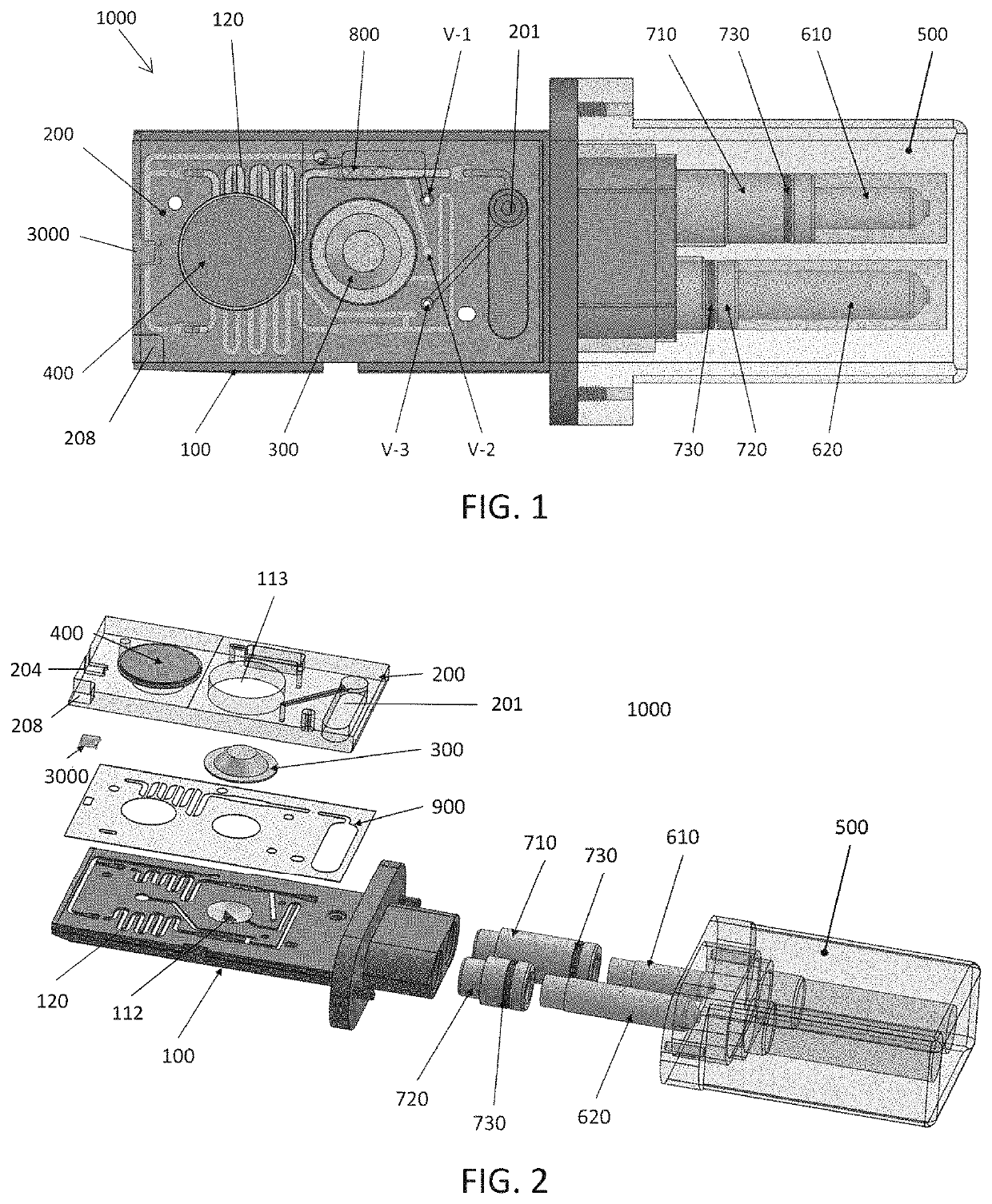
[0008]Described herein are methods and apparatuses for how to achieve robust optical performance of a sample cartridge reader with the use of polarization maintaining components in the optical path. The inherent nature of the optical coupling to almost any photonic chip is highly polarization dependent in addition to the propagation through waveguides and also evanescent coupling of light to molecules, including biological molecules. Thus by fixing the polarization state of all four excitation channels to the optical transverse-magnetic (TM) polarization as described herein, we may achieve optimal and reliable performance of our system.
[0009]This embodiment of the invention utilizes polarization-maintaining optical components in the optical path of the reader hardware. The excitation laser may be pigtailed with a polarization maintaining fiber and the scan head fiber is also polarization maintaining. With electromagnetic (EM) simulations of the photonic chip, we obtain the optimal polarization state (TM) to use with this photonic chip architecture. This leads to a stable and repeatable known polarization state of light exiting the scan head and coupling into the photonic chip.
[0031]The controller may be configured to control alignment of the scan head relative to the cartridge. For example, the cartridge holder may be configured to clamp the cartridge to prevent it from moving. In some variations, the cartridge holder may be configured to bias the cartridge in a direction that is normal to a major plane of the cartridge (e.g., in a y-axis direction) against a reference surface to prevent movement of the cartridge as one or more actuators apply force to the cartridge to drive fluid through the cartridge. This may reduce or eliminate misalignment of the chip relative to the scan head during operation. In any of these variations, the controller may be configured to adjust the position of the scan head during operation of the device by actuating a scan head actuator to align the ends of the optical fibers with waveguides of the photonic chip when the cartridge is in the cartridge holder.

Problems solved by technology

However, sending the samples to the lab and then waiting for the lab to process and testing the sample and then report the results can take a significant amount of time, typically at least days.

Method used


Image

  • Optical reader for analyte testing
  • Optical reader for analyte testing
  • Optical reader for analyte testing

Examples


examples

[0195]Example 1 FIGS. 15A and 15B shows results of an assay signal distribution as described herein for detecting marijuana (THC; tetrahydrocannabinol) in a sample. An assay is a balance between specificity and sensitivity: calling true negatives (TN; calling a result that was actually negative negative), false negatives (FN; calling a result negative when it was actually positive), false positives (FP; calling a result positive when it was actually negative) and true positives (calling a results positive when it was actually positive). FIG. 15A shows a graph of probability for (from L to R) true positives, false positives, false negatives, and true negatives using the systems and assays described herein. A threshold value of about 0.7× provides a balance between minimizing both false negatives and false positives (see the point at which these two curves overlap) and maximizing true negatives and true positives. Other threshold values could also or instead be chosen to increase / impr...


PUM

PropertyMeasurementUnit
lengthaaaaaaaaaa
lengthaaaaaaaaaa
lengthaaaaaaaaaa

Abstract

Analyte collection and testing systems and methods, and more particularly to disposable oral fluid collection and testing systems and methods. Described herein are methods and apparatuses to achieve significant improvements in the detection of fluorescence signals in the reader.

Description

CROSS REFERENCE TO RELATED APPLICATIONS[0001]This patent application claims priority to U.S. Provisional Patent Application No. 62 / 599,671, filed on Dec. 15, 2017 (titled “POLARIZATION MAINTAINING OPTICAL PATH FOR ENSURING READER TO READER CONSISTENCY”) and U.S. Provisional Patent Application No. 62 / 599,674, field on Dec. 15, 2017 (titled “CLAMP DESIGN FOR PRECISION ALIGNMENT OF THE CARTRIDGE”), each of which is herein incorporated by reference in its entirety[0002]This patent application may also be related to U.S. patent application Ser. No. 16 / 040,506, filed on Jul. 19, 2018, and now U.S. Pat. No. 10,660,619, titled (“CARTRIDGES FOR ORAL FLUID ANALYSIS AND METHODS OF USE”), which claims priority to U.S. Provisional Patent Application No. 62,534,394, titled “ORAL FLUID ANALYZING SYSTEMS AND METHODS” and filed Jul. 19, 2017.INCORPORATION BY REFERENCE[0003]All publications and patent applications mentioned in this specification are herein incorporated by reference in their entirety ...

Claims


Application Information

Patent Timeline
Patent Type & Authority Patents(United States)
IPC IPC(8): G01N33/94G01N33/487G01N21/64
CPCG01N33/94G01N21/6445G01N33/487G01N2021/6439G01N2201/0221G01N2201/0612G01N21/648G01N2021/6484G01N2201/0245G01N21/13G01N2021/135A61B10/0051G01N35/00029
Inventor SHASTRY, ASHUTOSHPIEHLER, DAVIDSANGHERA, HARDEEPGLUZCZACK, MICHAELCHOPRA, PRANAVCHANG, YUN-PEIKANTAK, AMEYA
Owner EVANOSTICS LLC
Learn More