Device for interventional acoustic imaging

a technology for interventional acoustic imaging and imaging devices, which is applied in the field of acoustic imaging, can solve the problems of significant percentage of cvs procedures described by physicians as difficult, and the visualization of interventional devices or devices employed in these procedures using existing acoustic probes and imaging systems is challenging, and achieves the effect of mitigating aberration artifacts

Active Publication Date: 2022-03-08
KONINKLJIJKE PHILIPS NV
View PDF26 Cites 0 Cited by
  • Summary
  • Abstract
  • Description
  • Claims
  • Application Information

AI Technical Summary

Benefits of technology

[0008]Desirable attributes for an acoustic imaging system and method include: accurate visualization of the instrument in the ultrasound image; enhanced imaging resolution at the location of intervention; and hands free operation of the acoustic probe.
[0010]Accordingly, it would be desirable to provide an ultrasound system, an acoustic probe, and a method which can provide enhanced acoustic imaging capabilities during interventional procedures.
[0013]In some versions of these embodiments, the acoustic imaging machine is further configured to use the feedback signal from the acoustic receiver to register a location of the acoustic receiver with respect to the acoustic echoes received by the acoustic probe, and to use the registration to mitigate aberration artifacts in the acoustic images
[0017]In another aspect of the invention, a method comprises: providing an acoustic probe comprising a substrate configured to be applied to the skin of a subject, the substrate having first and second principal surfaces with a diameter of at least approximately 12 cm and a shape of a concave disc which conforms to a shape of the skin where the acoustic probe is applied, the acoustic probe further having at least one device insertion port comprising an opening passing through the substrate from the first principal surface to the second principal surface, and an array of acoustic transducer elements supported by the substrate and disposed around the at least one device insertion port; providing transmit signals to least some of the acoustic transducer elements; the array of acoustic transducer elements transmitting an acoustic probe signal to an area of interest in the subject in response to the transmit signals; receiving at the acoustic probe acoustic echoes from the area of interest; receiving a feedback signal from an acoustic receiver provided at a distal end of an interventional device which passes through the device insertion port; using the feedback signal from the acoustic receiver to register a location of the acoustic receiver with respect to the acoustic echoes received by the acoustic probe; producing acoustic images of the area of interest in response to one or more signals received from the acoustic probe in response to the received acoustic echoes; and using the registration of the location of the acoustic receiver with respect to the acoustic echoes to mitigate aberration artifacts in the acoustic images.

Problems solved by technology

Visualization of an interventional device, or devices, (e.g., surgical instrument(s)) employed in these procedures using existing acoustic probes and imaging systems is challenging in many cases, and often requires manual repositioning of the acoustic probe during the procedure to maintain sufficient image quality.
A significant percentage of CVS procedures are described by the physician as difficult, and an even greater percentage are reported to have involved more than one insertion.
To address these problems, special interventional devices, such as echogenic needles, with enhanced visibility are successfully on the market and provide limited improvement at moderate extra cost.
Even with these improvements, certain clinical applications (e.g., deep nerve block) still remain largely or completely out of reach because of certain limitations to existing acoustic imaging probes and systems.
In many cases, anatomical features at the intervention site cannot be sufficiently resolved, especially for procedures which are performed at greater depths beneath the skin surface.
Acoustic imaging is also employed for deep nerve, but because existing systems cannot visualize these nerves, physicians use anatomical landmarks as guidance, making deep blocks much harder to perform.
Instrument visualization also can be poor due to specular reflection of device surface.

Method used


Image

  • Device for interventional acoustic imaging
  • Device for interventional acoustic imaging
  • Device for interventional acoustic imaging

Examples


Embodiment Construction

[0045]The present invention will now be described more fully hereinafter with reference to the accompanying drawings, in which preferred embodiments of the invention are shown. This invention may, however, be embodied in different forms and should not be construed as limited to the embodiments set forth herein. Rather, these embodiments are provided as teaching examples of the invention. Herein, when something is said to be “approximately” or “about” a certain value, it means within 10% of that value.

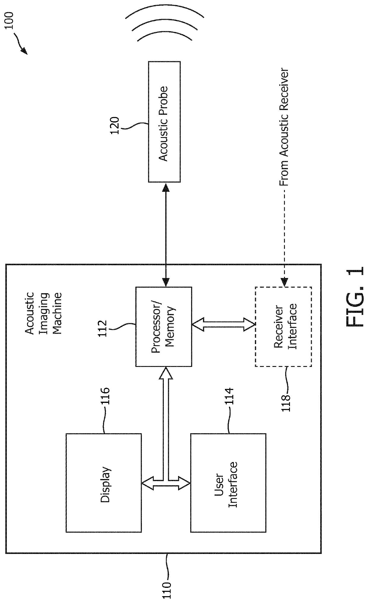
[0046]FIG. 1 shows one example of an acoustic imaging system 100 which includes an acoustic imaging machine 110 and an acoustic probe 120. Acoustic imaging machine 110 include a processor (and associated memory) 112, a user interface 114, a display 116 and optionally a receiver interface 118.

[0047]In various embodiments, processor 112 may include various combinations of a microprocessor (and associated memory), a digital signal processor, an application specific integrated circuit (ASIC...


PUM


Abstract

An acoustic probe connectable to an imaging system. The acoustic probe has a substrate with first and second principal surfaces, at least one device insertion port comprising an opening passing through the substrate from the first principal surface to the second principal surface, and an array of acoustic transducer elements supported by the substrate and disposed around the at least one device insertion port. The acoustic probe comprising an instrument guide disposed within the device insertion port, the instrument guide being configured to selectively allow the interventional device to move freely within the device insertion port and to selectively lock the interventional device within the device insertion port in response to a user input via a user interface connected to the acoustic probe.

Description

[0001]This application is the U.S. National Phase application under 35 U.S.C. § 371 of International Application No. PCT / EP2016 / 082935 filed on Dec. 30, 2016, which claims the benefit of Provisional Application Ser. No. 62 / 273,667 filed Dec. 31, 2015 and EP Application Serial No. 16157783.8, filed Feb. 29, 2016. These applications are hereby incorporated by reference herein.TECHNICAL FIELD[0002]This invention pertains to acoustic (e.g., ultrasound) imaging, and in particular a device and method for acoustic imaging in conjunction with an interventional procedure.BACKGROUND AND SUMMARY[0003]Acoustic (e.g., ultrasound) imaging systems are increasingly being employed in a variety of applications and contexts. For example, ultrasound imaging is being increasingly employed in the context of minimally invasive surgeries. This includes needle based procedures such as Chorionic Villus Sampling (CVS), needle based biopsies, and nerve blocks for local anesthesia. Today, typically the imaging ...

Claims


Application Information

Patent Timeline
Patent Type & Authority Patents(United States)
IPC IPC(8): A61B8/08A61B8/00A61B34/20A61B17/34
CPCA61B8/0841A61B8/4411A61B8/4455A61B8/4494A61B2017/3407A61B2017/3413A61B2034/2051A61B2034/2059
Inventor BHARAT, SHYAMERKAMP, RAMON QUIDONGUYEN, MANROBERT, JEAN-LUCHUANG, SHENG-WENKRUECKER, JOCHEN
Owner KONINKLJIJKE PHILIPS NV
Why Eureka
Try Eureka