Device for measuring the thickness of coatings

a coating and thickness technology, applied in the direction of measurement devices, electric/magnetic measuring arrangements, instruments, etc., can solve the problems of difficult change of relationship, limited useful frequency range in practice, scarce application of different measuring processes,

Active Publication Date: 2022-04-26
MICRO EPSILON MESSTECHNIK GMBH & CO KG
View PDF7 Cites 0 Cited by
  • Summary
  • Abstract
  • Description
  • Claims
  • Application Information

AI Technical Summary

Benefits of technology

[0017]According to a further aspect, the variation in the diameter of the rotationally symmetrical wall from the open end to the end plate may run constantly, preferably smoothly.

Problems solved by technology

In addition to this, particularly in the aviation sector, there are safety-relevant aspects in respect of lightning protection properties which require precise knowledge of the layer thickness, particularly on carbon-fibre-reinforced plastic, at which the application of different measuring processes is scarcely feasible.
The useful frequency range is limited in practice, e.g. also by legal guidelines.
Although the ratio of the change in frequency to the change in length can be influenced by a change in the cavity length or the cavity diameter within certain limits, many marginal conditions have to be observed in practice, which make this relationship difficult to change, in particular competing natural oscillations.
These degenerated modes are in some cases non-rotationally symmetrical, which in the case of a non-isotropic substrate results in the measuring result changing if the measuring unit is rotated (about the axis of the cylinder), i.e. the measuring unit is not “non-rotatable”.

Method used


Image

  • Device for measuring the thickness of coatings
  • Device for measuring the thickness of coatings
  • Device for measuring the thickness of coatings

Examples


Embodiment Construction

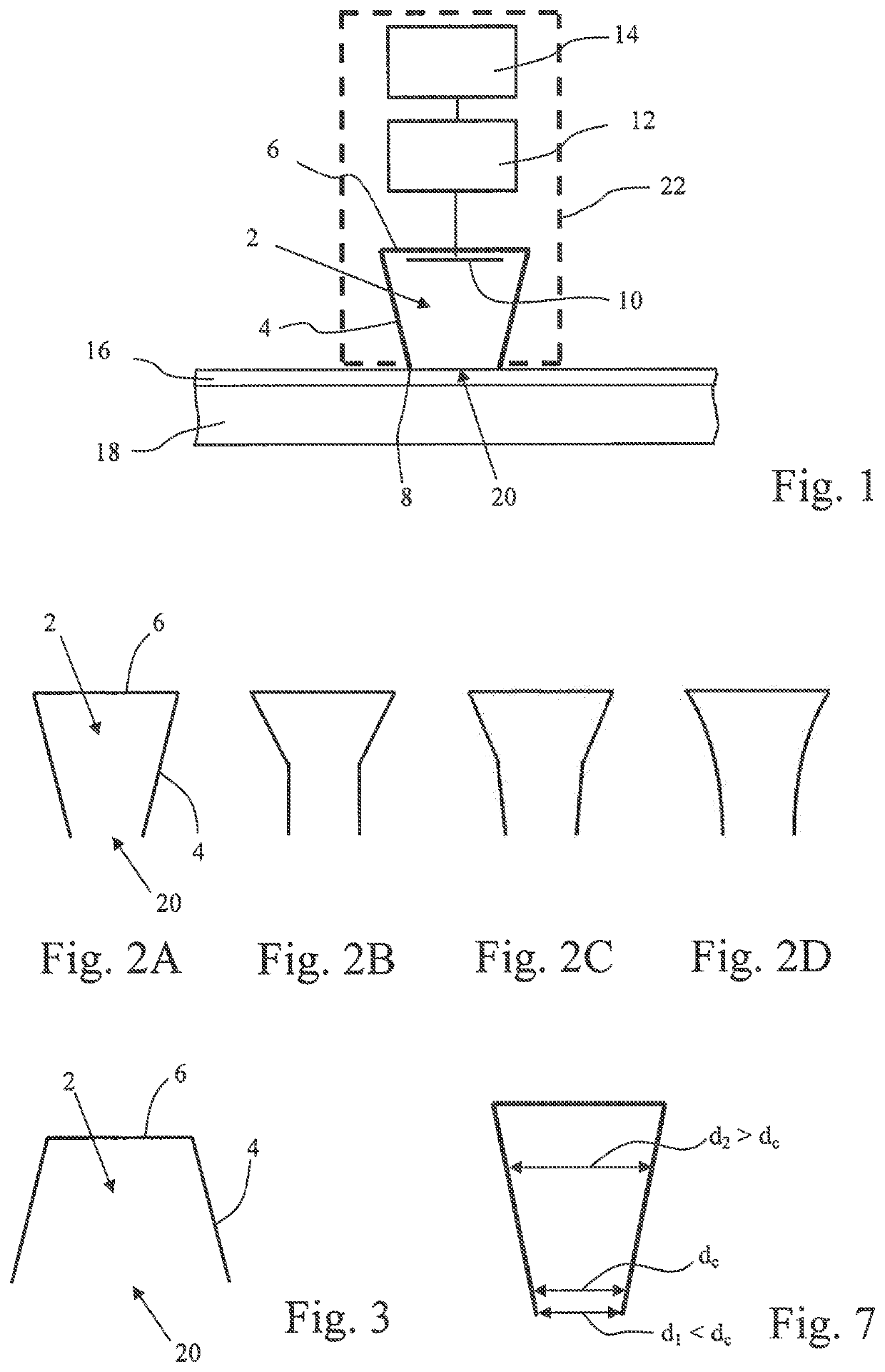
[0037]FIG. 1 shows a diagram of an embodiment of the measuring device according to the invention in section. An end plate 6 (or end wall) and a rotationally symmetrical wall 4 form a resonance cavity 2 for electromagnetic (wave) fields which is open at one end 8, wherein the diameter of the rotationally symmetrical wall 6 is not constant. The rotationally symmetrical wall 4 and the end plate 6 are made of a conductive material (metal). The resonance cavity 2 is adapted to be positioned with the open end 8 which lies opposite the end plate 6 on a dielectric layer 16 which is located on a substrate 18 made of a conductive material and the thickness whereof is to be measured. Furthermore, the device comprises an antenna 10 which is adapted to excite an electromagnetic field in the resonance cavity 2.

[0038]The end plate 6 and the rotationally symmetrical wall 4 are conductive and therefore form together with the substrate 18 a substantially closed cavity (“substantially” since the diele...


PUM

PropertyMeasurementUnit
frequenciesaaaaaaaaaa
half opening angleaaaaaaaaaa

Abstract

The present invention relates to a measuring device for determining the thickness of a dielectric layer on a conductive substrate. The device comprises a resonance cavity for electromagnetic fields which has a rotationally symmetrical wall, an end plate and an open end and is adapted to be positioned with the open end on the dielectric layer. The device further comprises an antenna which is adapted to excite an electro-magnetic field in the resonance cavity, a reflection measuring unit for determining at least one property of the electromagnetic field and an evaluation circuit for determining the thickness of the dielectric layer from the at least one property of the electromagnetic field. A diameter of the rotationally symmetrical wall varies in a longitudinal direction of the resonance cavity.

Description

FIELD OF THE INVENTION[0001]The present invention relates to a measuring device for determining the thickness of dielectric layers, e.g. a coat of paint or lacquering, on a conductive substrate by means of high-frequency electromagnetic fields in a resonance cavity.STATE OF THE ART[0002]In many industrial applications, e.g. in aircraft or motor vehicle construction, it is necessary for the thickness of dielectric layers applied to a conductive base material or substrate, which are intended to reduce corrosion or air resistance or are for decorative purposes, for example, to be accurately determined. In addition to this, particularly in the aviation sector, there are safety-relevant aspects in respect of lightning protection properties which require precise knowledge of the layer thickness, particularly on carbon-fibre-reinforced plastic, at which the application of different measuring processes is scarcely feasible. The thickness measurement should take place in a non-destructive ma...

Claims


Application Information

Patent Timeline
Patent Type & Authority Patents(United States)
IPC IPC(8): G01B7/06G01B15/02
CPCG01B7/105G01B15/02
Inventor ZIEP, CHRISTIANRICHTER, MAIKHINKEN, JOHANN
Owner MICRO EPSILON MESSTECHNIK GMBH & CO KG
Why Eureka
Try Eureka