Anti-Ovalization Tool for Introduction Into a Wind Turbine Blade Root and Method of Reducing Ovalization of a Wind Turbine Blade Root

a technology of wind turbine blades and root, which is applied in the direction of propellers, water-acting propulsive elements, lamination, etc., can solve the problems of insufficient resin cure, blades may still be relatively soft, and composite materials may not have the structural integrity to provide a secure fixing mechanism, etc., to achieve the effect of reducing unwanted deformation

Active Publication Date: 2013-07-18
GE RENEWABLE TECH WIND BV
View PDF4 Cites 0 Cited by
  • Summary
  • Abstract
  • Description
  • Claims
  • Application Information

AI Technical Summary

Benefits of technology

[0024]In some cases, the step of introducing the anti-ovalization tool inside the blade root may be carried out substantially directly after joining the two blade halves together. In others, it may be carried out substantially directly before joining the two blade halves together. In order to reduce unwanted deformation, the anti-ovalization tool is preferably introduced before the deformation takes place. In certain implementations however, the distances between the rigid bodies may be “over-adjusted”, such that the rigid bodies exert a pressure against the inner blade wall that can undo an unwanted deformation.
[0025]In some implementations, the anti-ovalization tool may be shaped such as to allow a small deformation of the blade root.

Problems solved by technology

Such composite materials may not have the structural integrity to provide a secure fixing mechanism into which, for example, threaded bolts may be directly inserted.
In these cases, the resin may not be fully cured yet and the blades may still be relatively soft.
Both things may cause a deformation of the blade root portion of the blade that may lead to incompatibilities between the hub and the blade root or to a cumbersome blade mounting process.
Although composite materials reduce the blades' weight, it is important to consider the fact that a finished blade, made of composite, still has a considerable weight.
Therefore, a problem derived from above mentioned storage time is that the blade root portion may deform in the storage position due to the weight of the whole blade.
In practice, a deformation of the blade root portion of a blade can at least complicate the blade mounting process and it can also lead to a more vulnerable attachment at the hub.
In operation, they thus may be subjected to transverse loads, potentially shortening their lifetime and the lifetime of the blades.

Method used


Image

  • Anti-Ovalization Tool for Introduction Into a Wind Turbine Blade Root and Method of Reducing Ovalization of a Wind Turbine Blade Root
  • Anti-Ovalization Tool for Introduction Into a Wind Turbine Blade Root and Method of Reducing Ovalization of a Wind Turbine Blade Root
  • Anti-Ovalization Tool for Introduction Into a Wind Turbine Blade Root and Method of Reducing Ovalization of a Wind Turbine Blade Root

Examples


Embodiment Construction

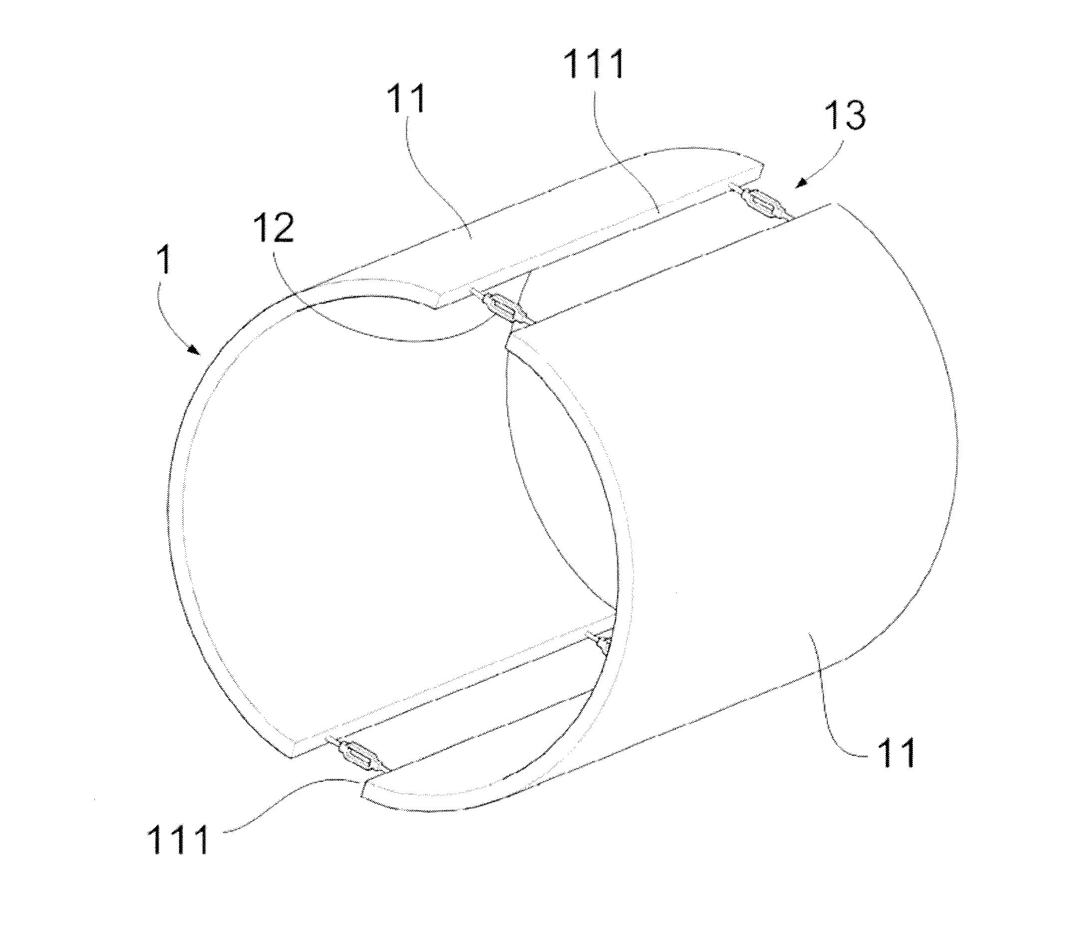
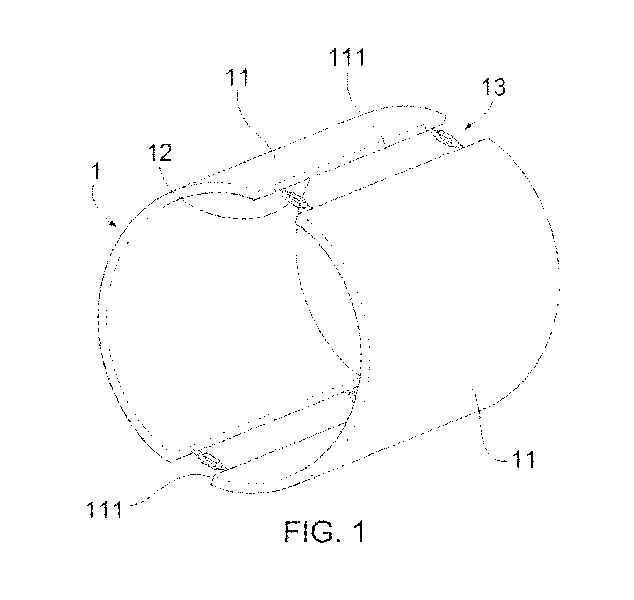
[0032]FIG. 1 shows a perspective view of an anti-ovalization tool according to a first embodiment. The anti-ovalization tool 1 may comprise two substantially semi-cylindrical rigid bodies 11. The rigid bodies 11 may be connected to each other by their side edges 111 with four turnbuckles 12, leaving two gaps 13 in between them. Together the rigid bodies 11 may form a substantially cylindrical body and their side edges 111 may extend parallel to a central axis of the cylinder.

[0033]It should be noted, that in other implementations, the tool may comprise more than two rigid bodies. In such cases the rigid bodies may form together a substantially cylindrical body leaving more than two gaps in between their side edges. In other implementations, such gaps may be filled with a deformable material. In further embodiments, naturally a different number of turnbuckles may be used.

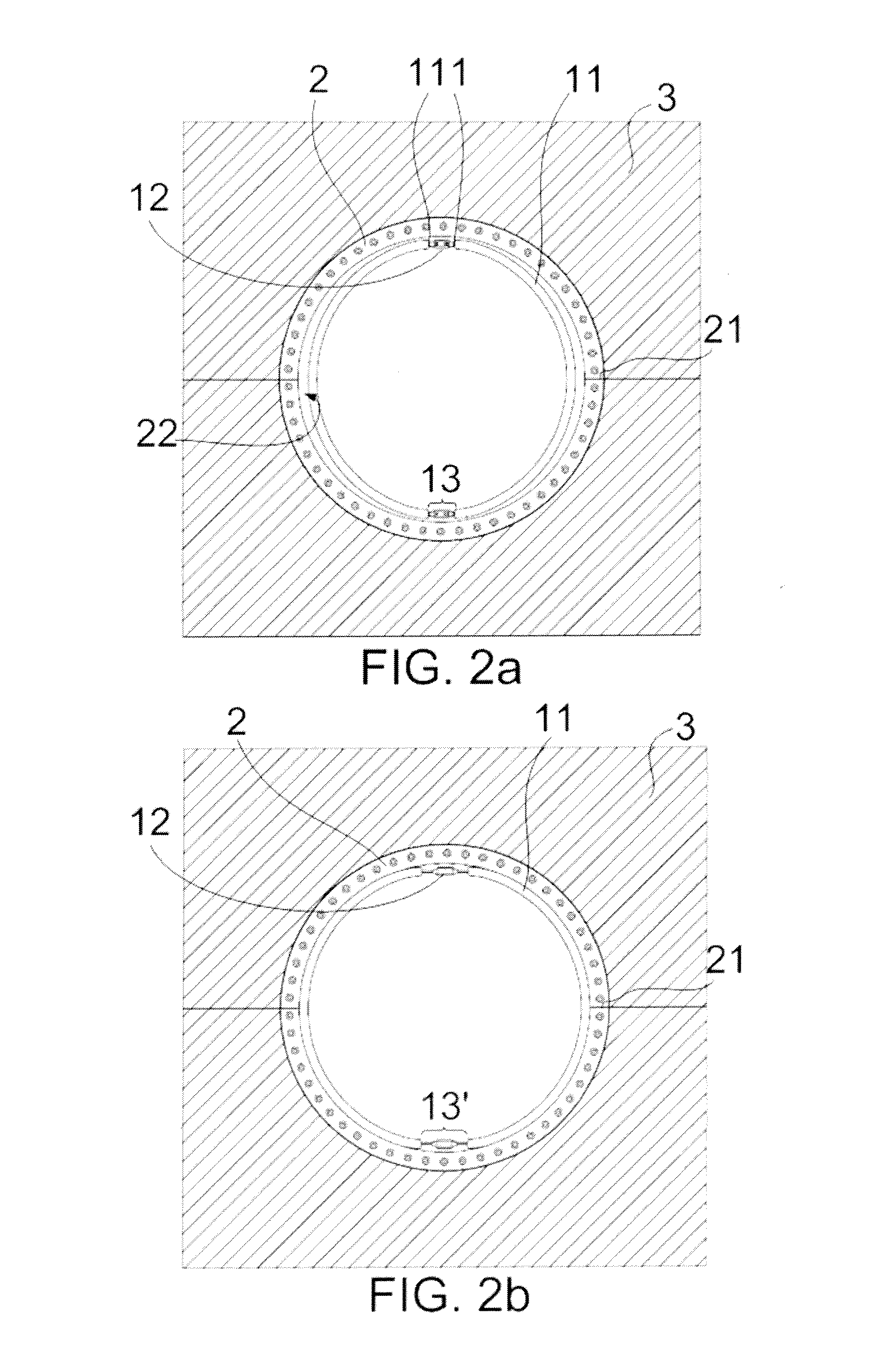
[0034]It is noted that by adjusting the distances between the side edges of the rigid bodies, the shape of the too...


PUM

PropertyMeasurementUnit
thicknessaaaaaaaaaa
lengthaaaaaaaaaa
distancesaaaaaaaaaa

Abstract

Anti-ovalization tool for introduction into a wind turbine blade root comprising two or more rigid bodies connected to one another along their side edges with distances in between them and together forming a substantially cylindrical body, wherein the distances between the rigid bodies are adjustable. The invention is further related to the method of reducing ovalization of a wind turbine blade root and to the use of a tool comprising two or more rigid bodies as an anti-ovalization tool.

Description

[0001]This application claims the benefit of European Patent Application 12382014.4 filed on Jan. 17, 2012 and U.S. Provisional Patent Application Ser. No 61 / 612,799 filed on Mar. 19, 2012.[0002]The present invention relates to an anti-ovalization tool for introduction into a wind turbine blade root. The invention further relates to a wind turbine blade and to a wind turbine comprising such a tool.[0003]Furthermore, the invention relates to a method of reducing ovalization of a wind turbine blade root.BACKGROUND ART[0004]The blades in a wind turbine are typically attached, at a blade root portion, to a rotor hub, either directly or through an extender.[0005]Typically, the blades are made from composite materials: reinforcing fibres may be bonded to one another with a resin and, subsequently, cured to consolidate. Different kinds of fibres (e.g. glass, carbon, combinations) and resins (e.g. epoxy) may be used in different forms (e.g. prepreg, fibre sheets). Such composite materials m...

Claims


Application Information

Patent Timeline
Patent Type & Authority Applications(United States)
IPC IPC(8): F03D1/00
CPCF03D11/00F03D1/005Y02E10/721F03D1/001Y02E10/722F03D1/0675F03D80/00F03D13/10F03D13/40Y02E10/72
Inventor GIUFFRE, GIAN PIERO
Owner GE RENEWABLE TECH WIND BV
Why Eureka
Try Eureka