Hollow Core Optical Fiber And Method Of Making The Same

Active Publication Date: 2020-10-08
OFS FITEL LLC
View PDF0 Cites 2 Cited by
  • Summary
  • Abstract
  • Description
  • Claims
  • Application Information

AI Technical Summary

Benefits of technology

[0005]The problems remaining in the prior art are addressed by the present invention, which relates to a hollow core photonic bandgap optical fiber and, more partic

Problems solved by technology

While theoretically possible to support propagation of optical signals across the full spectrum of wavelengths within the band gap, it has been found in practice that guiding light over the entire wavelength range of the band gap is diff

Method used


Image

  • Hollow Core Optical Fiber And Method Of Making The Same
  • Hollow Core Optical Fiber And Method Of Making The Same
  • Hollow Core Optical Fiber And Method Of Making The Same

Examples


Example

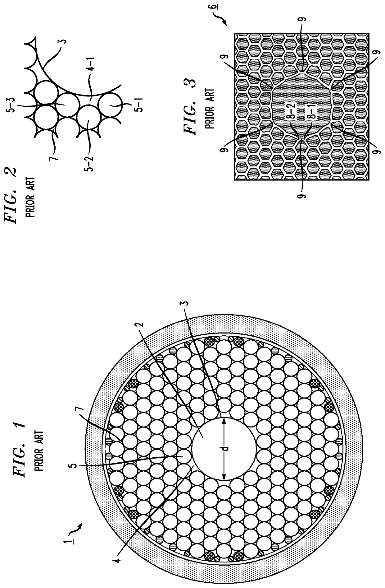
[0022]An assembly of various capillary tubes and glass rods used to form a conventional hollow core optical fiber is shown in the prior art illustration of FIG. 1. The capillary tubes are represented as open circles and the rods (disposed around the outer periphery of the assembly) are represented as closed (filled-in) circles. In this particular assembly 1, a set of nineteen capillary tubes has been removed from the central area to define a hollow core region 2. A core tube 3 is inserted within this space and is used to support the structure during subsequent draw processes so as to maintain an open (hollow) core region 2. As shown in FIG. 1, core tube 3 does not completely fill the periphery of hollow core region 2, with interstitial spaces 4 remaining at various locations between core tube 3 and those capillaries 5 immediately adjacent to core tube 3. FIG. 2 is an enlargement of a portion of the structure shown in FIG. 1, clearly illustrating selected interstitial spaces 4 at the...


PUM

PropertyMeasurementUnit
Fractionaaaaaaaaaa
Fractionaaaaaaaaaa
Fractionaaaaaaaaaa

Abstract

The selection of starting materials used in the process of forming an MCR is controlled to specifically define the physical properties of the core tube and/or the capillary tubes in the local vicinity of the core tube. The physical properties are considered to include, but are not limited to, the diameter of a given tube/capillary, its wall thickness, and its geometry (e.g., circular, non-circular). A goal is to select starting materials with physical properties that yield a final hollow core optical fiber with a “uniform” core region (for the purposes of the present invention, a “uniform” core region is one where the struts of cladding periodic array surrounding the central core are uniform in length and thickness (with the nodes between the struts thus being uniformly spaced apart), which yields a core wall of essentially uniform thickness and circularity.

Description

TECHNICAL FIELD[0001]The present invention relates to hollow core photonic bandgap optical fiber and, more particularly, to fabrication techniques for improving the circularity and uniformity of the core region in this type of optical fiber.BACKGROUND OF THE INVENTION[0002]Light is confined within a hollow core optical fiber via the photonic band gap effect. This guidance mechanism is unique in that light can be confined to a core with a refractive index that is lower than the refractive index of the surrounding cladding material. The cladding of a hollow core optical fiber is formed by a periodic array of air holes that run longitudinally along the length of the fiber. With a sufficiently large enough diameter hole, an out-of-plane band gap is created. For the purposes of the present invention, a “band gap” is defined as a range of wavelengths and angles within the periodic array structure that cannot support any modes of a propagating optical signal. Therefore, any light incident ...

Claims


Application Information

Patent Timeline
IPC IPC(8): G02B6/02C03B37/027
CPCG02B6/02328C03B37/0279C03B37/0122C03B2203/42C03B2203/14C03B2203/12C03B37/02781
Inventor MANGAN, BRIAN
Owner OFS FITEL LLC
Why Eureka
Try Eureka