
Methods of manufacturing a hermetic and isolating feedthrough for an electronic device casing, in particular made of titanium

a technology of electronic devices and feedthroughs, which is applied in the direction of feed-through capacitors, capacitors, therapy, etc., can solve the problems of high cost, large number of successive implementations, and relatively complex implementations, and achieve the effect of robust mechanical holding

Active Publication Date: 2022-05-03
MISTIC
View PDF7 Cites 0 Cited by
  • Summary
  • Abstract
  • Description
  • Claims
  • Application Information

AI Technical Summary

Benefits of technology

[0019]The problem of the invention is to remedy these drawbacks and limitations of prior art by a new means of making a monolithically integrated feedthrough with a micrometric lateral vertical isolation that can guarantee a robust mechanical holding between two portions of a same substrate, by original mechanisms of mechanical holding of the islet during and after the process, with a particular sequence of manufacturing steps that, in particular, requires no general thinning down of the substrate after the steps of islet shaping and controlled oxidation, as in the case of the known techniques described hereinabove, through a thickness that may reach at least 100 to 150 μm, compatible with the making of feedthroughs integrated into an implantable device casing, and that, while guaranteeing perfect hermeticity and mechanical stability to the unit obtained.
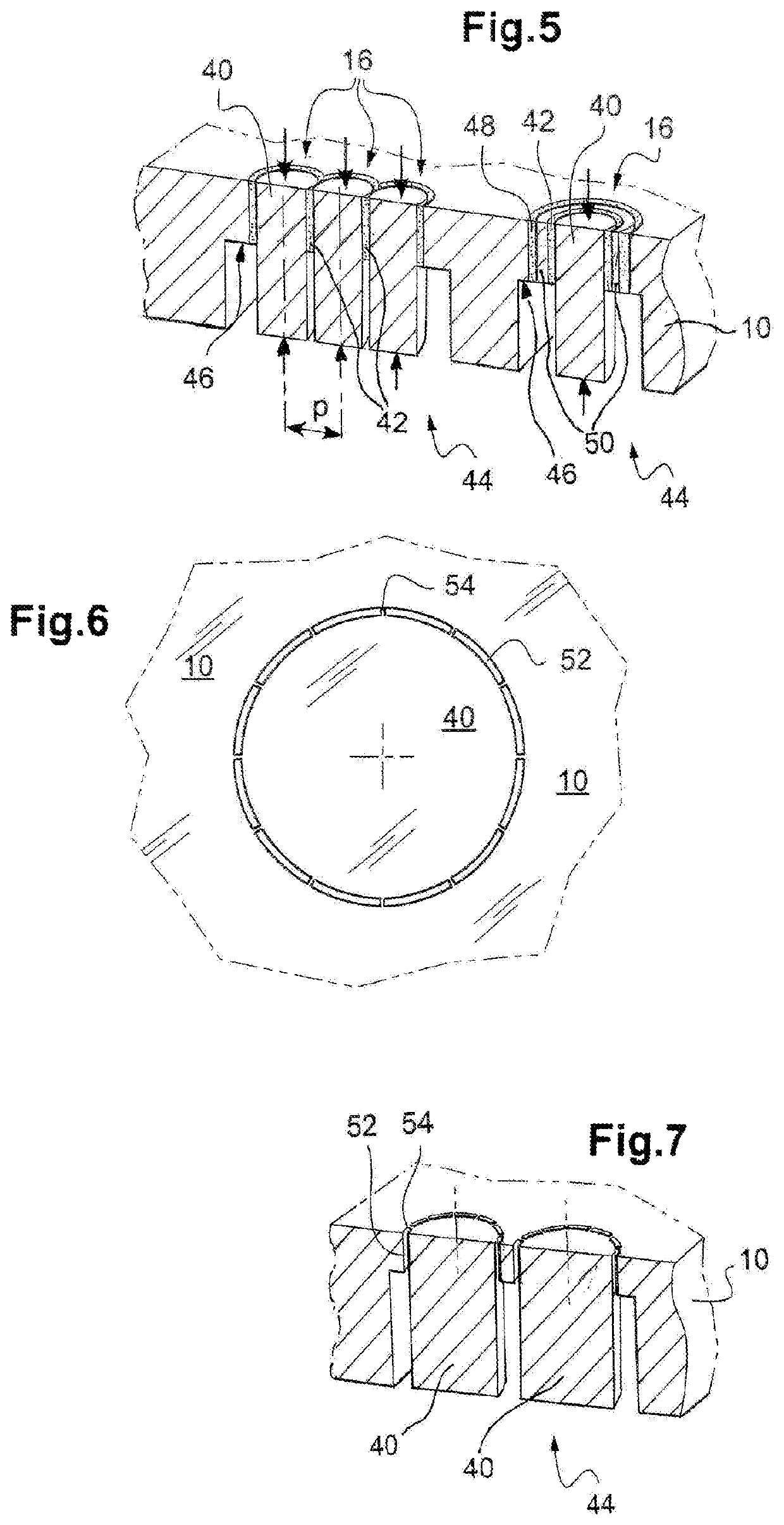
[0020]The invention has also for object to allow the making of multiple, very close, feedthroughs, having an extremely reduced center-to-center pitch between adjacent feedthroughs, with consequently the possibility to highly miniaturize the device into which these feedthroughs are integrated and / or to gather the feedthroughs in an area of reduced extent, with a very high density of contacts.

Problems solved by technology

The technologies implemented are however relatively complex and involve a multiplicity of successive steps, not only for making the feedthroughs but also for subsequently assembling each of them into the casing while guaranteeing the strongest and the most reliable possible mechanical connection.
Besides complexity, and consequently high cost, these technologies also suffer from a number of drawbacks resulting in particular from the fact that it is not possible to place the different adjacent feedthroughs as close as it would be desirable.
However, to provide the required mechanical strength, the hanging by one or several upper layers requires the deposition of relatively thick layers (about 10 μm per layer) with respect to the conventional deposition methods used in the integrated-circuit technology, which turns out to be expensive.
The thick layers may also generate a high level of mechanical stresses and a significant deformation of the substrate, which may make the manufacture complicated and have a negative effect on the reliability of the structure obtained.
This stopgap nevertheless requires an additional step and hence increases the cost of manufacturing, and moreover leads to handling suspended structures, which are still rather fragile despite the plurality of support layers.
Finally, a potential interaction between additional isolating and conductive layers may lead to a loss of electrical isolation over time.
To guarantee the performances of the feedthrough during the whole lifetime of the device, it may then be necessary to add intermediate sub-layers that will limit the diffusions between neighbor layers, which increases even more the complexity of the structure and hence its cost of manufacturing.
The implementation of this other technique nevertheless suffers from antagonist and irreconcilable technological and conceptual difficulties.
Now, the engraving technologies do not allow obtaining profiles with such small shape factors (ratio between opening and depth of engraving).

Method used


Image

  • Methods of manufacturing a hermetic and isolating feedthrough for an electronic device casing, in particular made of titanium
  • Methods of manufacturing a hermetic and isolating feedthrough for an electronic device casing, in particular made of titanium
  • Methods of manufacturing a hermetic and isolating feedthrough for an electronic device casing, in particular made of titanium

Examples


Embodiment Construction

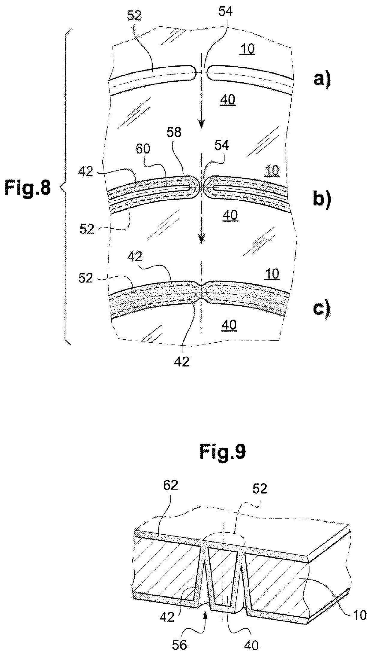
[0071]After a description of prior art, various examples of feedthroughs as well as two methods of making such feedthroughs using the teachings of the invention will be explained.

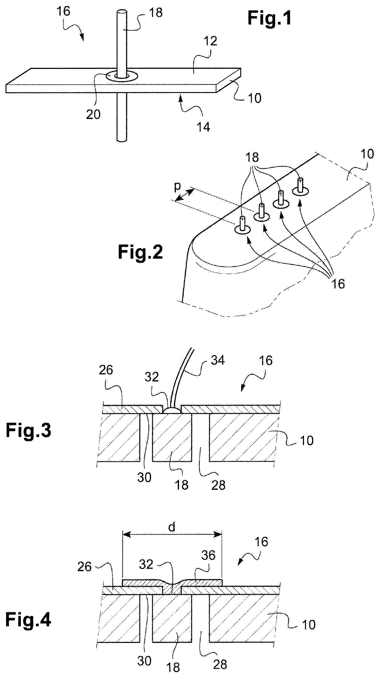
[0072]Feedthrough Structure with a Central Islet Held by a Bridge of Material

[0073]FIGS. 1 to 4 illustrate a prior art structure. In FIG. 1 is illustrated the principle of a feedthrough, which is intended to allow the passage of an electric connection through an electrically conductive wall including a metallic substrate 10, typically made of titanium.

[0074]The metallic substrate 10 includes an upper face 12 and a lower face 14 (these two terms referring only to the presentation of the figures, without limitative connotation; it will be the same for the adjectives “outer” and “inner” used to denote respectively these two same sides with respect to a casing, the substrate 10 forms a wall of which). The feedthrough 16 includes an electrically conductive metal through-element 18, fully isolated from the remain...


PUM


Abstract

A device casing includes a wall having a metallic substrate and electrical connection of a feedthrough that includes a metal through-element made at least in a zone of isolation of the area of the feedthrough from the substrate material, in the form of an islet of closed contour, physically and electrically isolated from the substrate. An interface for coupling the through-element to the substrate provides the mechanical securing of the through-element to the substrate and the electrical isolation thereof and includes a peripheral lateral layer made of an electrically isolating material that surrounds the through-element over the whole periphery thereof and extends transversally through the thickness of the thinned area of the substrate. The substrate, the through-element and the lateral layer form a monolithically integrated unit, and the lateral layer provides essentially and directly both the mechanical securing and the electrical isolation between through-element and substrate.

Description

CROSS REFERENCE TO RELATED APPLICATIONS[0001]This application claims priority under 35 U.S.C. § 119(a) to French Patent Application Serial Number 1759208, filed Oct. 3, 2017, the entire teachings of which are incorporated herein by reference.BACKGROUND OF THE INVENTIONField of the Invention[0002]The invention relates to the technique for designing and manufacturing components or component parts called “feedthroughs”, which are hermetic and electrically isolated passages for an electrical connection through a metal wall.Description of the Related Art[0003]In feedthroughs, a metal wall may be the casing of an electronic device. The feedthroughs then allow electrical connections to be made between the inner volume of the casing (inner side of the feedthrough), which for example contains electronic circuits, and an exposed surface of this same casing (outer side of the feedthrough). The electrical connection includes a conductive, metal through-element. The casing being metallic, and he...

Claims


Application Information

Patent Timeline
Patent Type & Authority Patents(United States)
IPC IPC(8): A61N1/37A61N1/375H01G2/10H01G4/236H01G4/35H02G3/22
CPCA61N1/375A61N1/3752A61N1/3754H01G2/103H01G4/236H01G4/35H02G3/22
Inventor BOUTAUD, BERTRAND
Owner MISTIC
Learn More