Apparatus and method for modifying a loudspeaker signal for preventing diaphragm over-deflection

a technology of diaphragm and loudspeaker, which is applied in the direction of transducer type, transducer circuit damping, biological neural network models, etc., can solve the problems of excessive deflection of mechanical components of sound transducers, poor sound quality, and damage to loudspeakers (independent of actuator principles) and achieves good mechanical protection, small power, and optimized sound quality

Active Publication Date: 2022-05-03
FRAUNHOFER GESELLSCHAFT ZUR FOERDERUNG DER ANGEWANDTEN FORSCHUNG EV
View PDF21 Cites 0 Cited by
  • Summary
  • Abstract
  • Description
  • Claims
  • Application Information

AI Technical Summary

Benefits of technology

[0016]This embodiment of the apparatus is based on the finding that by considering both the current time block as well as the subsequent time block, the diaphragm deflection signal of the current time block is not attenuated too little or too much compared to the subsequent diaphragm deflection signal block, whereby high sound quality can be obtained. Here, by the comparison-based attenuation of overlapping diaphragm deflection signal blocks, the apparatus can consider an overlap-add (e.g., a segmented convolution of modified diaphragm deflection signal blocks of successive time blocks), by which a common diaphragm deflection signal can result in the overlap area of the current diaphragm deflection signal block with the subsequent diaphragm deflection signal block, which should comprise a deflection amplitude that is lower than the diaphragm over-deflection so that mechanical protection can be ensured. For this, the apparatus can determine the level up to which the diaphragm deflection signal block can be controlled to attenuate the current diaphragm deflection signal block compared to the subsequent diaphragm deflection signal block in an optimized ratio. The level is determined, for example, at the temporal position of the maximum deflection, since at this temporal position, e.g., diaphragm over-deflection can occur and hence the level can be determined such that the current diaphragm deflection signal block is attenuated such that a maximum diaphragm deflection amplitude can be obtained at this temporal position, e.g., after the overlap-add. Thus, the modified current diaphragm deflection signal block can be obtained, which can ensure that the loudspeaker signal synthesized therefrom, e.g., the diaphragm of the loudspeaker to which the synthesized loudspeaker signal can be transmitted, cannot be damaged by diaphragm over-deflection and the loudspeaker can be operated at high performance, e.g., by using the complete possible deflection of the diaphragm (e.g., up to the maximum diaphragm deflection amplitude) without diaphragm over-deflection.
[0041]According to an embodiment, the predetermined fading-away function can comprise shorter time constants for the percussive signal portion than for the harmonic signal portion.

Problems solved by technology

Basic problem: loudspeakers (independent of the actuator principle) may be damaged or destroyed due to excessive mechanical load.
Generally, this takes place when applying a high input voltage resulting in excessive deflection of the mechanical components of the sound transducer (diaphragm, suspension, .
Problems of a simple solution: simple limiters result in poor sound quality and cannot guarantee the mechanical protection of the transducer, or need too much headroom, which does not fully utilize the performance of the transducer.
A disadvantage of the filter design is that frequency portions that are insignificant for diaphragm deflection may be extracted from the signal.
This effects an unnecessary deterioration of the sound quality.
A further difficulty is the reaction time of the individual blocks.
Thus, impulse-like signal portions are difficult to correct.
This can take place, for example, by means of attack, hold and release functions and can result in an optimization of the sound quality.

Method used


Image

  • Apparatus and method for modifying a loudspeaker signal for preventing diaphragm over-deflection
  • Apparatus and method for modifying a loudspeaker signal for preventing diaphragm over-deflection
  • Apparatus and method for modifying a loudspeaker signal for preventing diaphragm over-deflection

Examples


Embodiment Construction

[0055]Embodiments according to the present invention will be discussed in more detail below with reference to the accompanying drawings. Regarding the illustrated schematic figures, it should be noted that the illustrated functional blocks can be considered both as elements or features of the inventive apparatus and as respective method steps of the inventive method and respective method steps of the inventive method can also be derived therefrom. Before embodiments of the present invention will be discussed in more detail below with reference to the drawings, it should be noted that identical, functionally equal or equal elements, objects and / or structures in the different figures are provided with the same or similar reference numbers in the different figures such that the description of these elements illustrated in different embodiments is inter-exchangeable or inter-applicable.

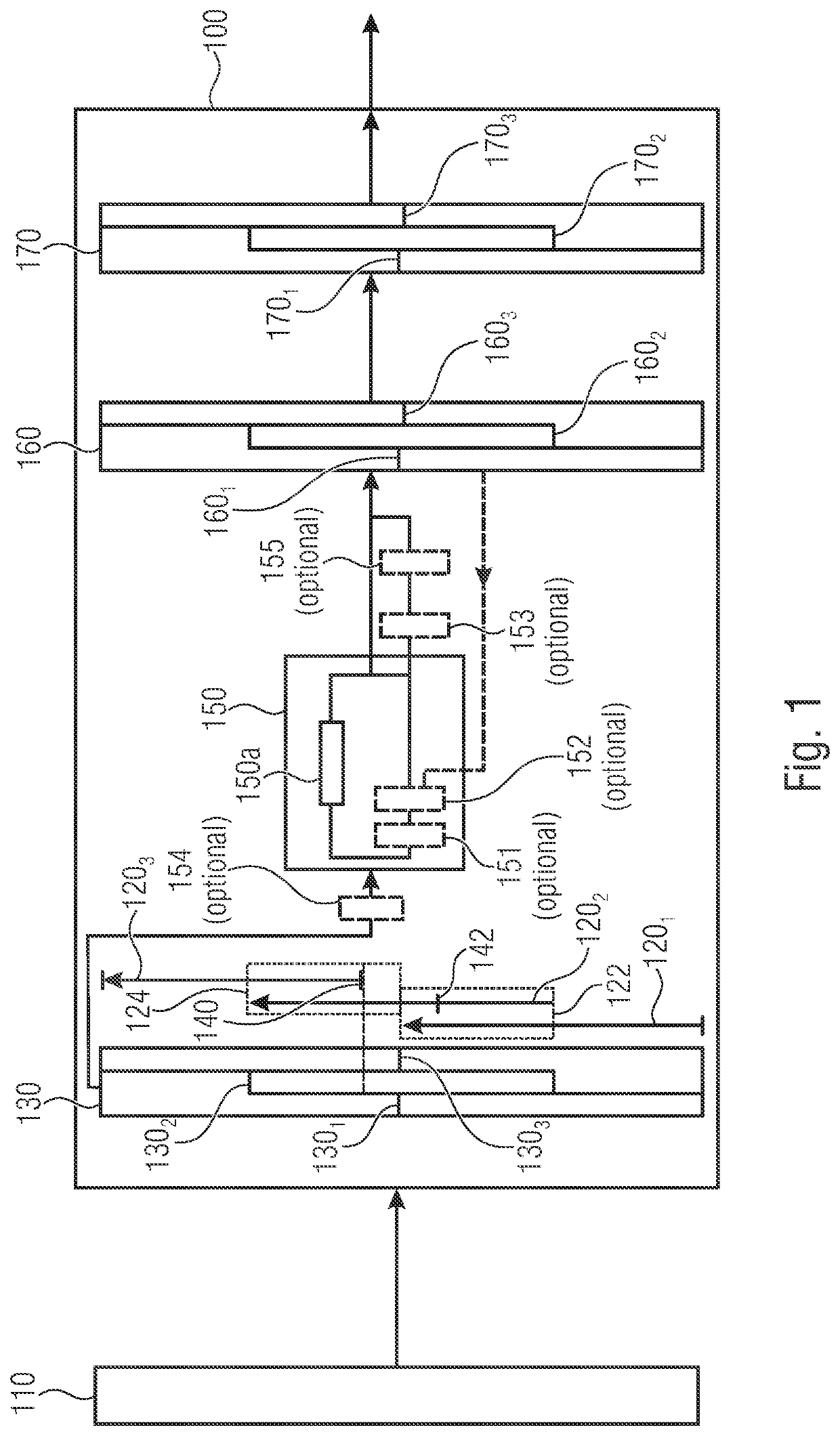
[0056]FIG. 1 shows a schematic illustration of an apparatus 100 for modifying a loudspeaker signal 110...


PUM


Abstract

Apparatus configured to predict a diaphragm deflection signal, block-by-block, in overlapping time blocks based on the loudspeaker signal to obtain one diaphragm deflection signal block per time block. The apparatus is configured to determine a temporal position of a maximum deflection of a current diaphragm deflection signal block of a current time block within an overlap area with a subsequent time block and to calculate a level up to which the current diaphragm deflection signal block can be controlled without diaphragm over-deflection for the current time block by considering a comparison of the current diaphragm deflection signal block with a subsequent diaphragm deflection signal block or an estimation of the subsequent diaphragm deflection signal block from the current diaphragm deflection signal block at the temporal position. The apparatus is configured to attenuate the current diaphragm deflection signal block and to synthesize a modified loudspeaker signal.

Description

CROSS-REFERENCE TO RELATED APPLICATIONS[0001]This application is a continuation of copending International Application No. PCT / EP2019 / 067591, filed Jul. 1, 2019, which is incorporated herein by reference in its entirety, and additionally claims priority from German Applications Nos. 102018210872.2, filed Jul. 2, 2018, and 102018213834.6, filed Aug. 16, 2018, which are all incorporated herein by reference in their entirety.[0002]Embodiments according to the invention relate to an apparatus and a method for modifying a loudspeaker signal for preventing diaphragm over-deflection. In other words, this can be a deflection limiter, for example.BACKGROUND OF THE INVENTION[0003]Basic problem: loudspeakers (independent of the actuator principle) may be damaged or destroyed due to excessive mechanical load. Generally, this takes place when applying a high input voltage resulting in excessive deflection of the mechanical components of the sound transducer (diaphragm, suspension, . . . ).[0004]...

Claims


Application Information

Patent Timeline
Patent Type & Authority Patents(United States)
IPC IPC(8): H04R3/02H04R7/00H04R3/00G06N3/02
CPCH04R3/02H04R3/007H04R7/00G06N3/02H04R3/002
Inventor RITTER, ROBINMAENNCHEN, ANDREAS
Owner FRAUNHOFER GESELLSCHAFT ZUR FOERDERUNG DER ANGEWANDTEN FORSCHUNG EV
Why Eureka
Try Eureka