Surface-coated cutting tool and method for manufacturing same

a cutting tool and surface coating technology, applied in the manufacturing of gear teeth, superimposed coating processes, gear teeth, etc., can solve the problems of cutting edge wear and breakage, and achieve the effect of excellent breakage resistan

Active Publication Date: 2022-05-10
SUMITOMO ELECTRIC HARDMETAL CORP
View PDF30 Cites 0 Cited by
  • Summary
  • Abstract
  • Description
  • Claims
  • Application Information

AI Technical Summary

Benefits of technology

[0029]According to the description above, there can be provided a surface-coated cutting tool having excellent breakage resistance and wear resistance.

Problems solved by technology

During the cutting, the cutting edge of such a cutting tool is exposed to a severe environment such as high temperature and high stress, thus resulting in wear and breakage of the cutting edge.

Method used


Image

  • Surface-coated cutting tool and method for manufacturing same
  • Surface-coated cutting tool and method for manufacturing same

Examples


examples

[0137]While the present disclosure will be described in more detail hereinafter with reference to Examples, the present disclosure is not limited thereto.

[0138]>

[0139]

[0140]First, as substrates on which coating films were to be formed, substrates K and substrates L shown in Table 1 below were prepared (the step of preparing the substrate). Specifically, first, source material powders in a blending composition (mass %) described in Table 1 were mixed uniformly. The expression “Remainder” in Table 1 indicates that WC is a remainder of the blending composition (mass %).

[0141]

TABLE 1Blending Composition (Mass %)TypeCoCr3C2WCSubstrateK7.00.3RemainderL12.00.5Remainder

[0142]Next, the mixed powders were pressed and molded into a predetermined shape and were then sintered at 1300 to 1500° C. for 1 to 2 hours, thereby obtaining substrates K each composed of cemented carbide (substrate shape (JIS): CNMG120408-EX) and substrates L each composed of cemented carbide (substrate shape (JIS): SEET13...


PUM

PropertyMeasurementUnit
thicknessaaaaaaaaaa
thicknessaaaaaaaaaa
thicknessaaaaaaaaaa

Abstract

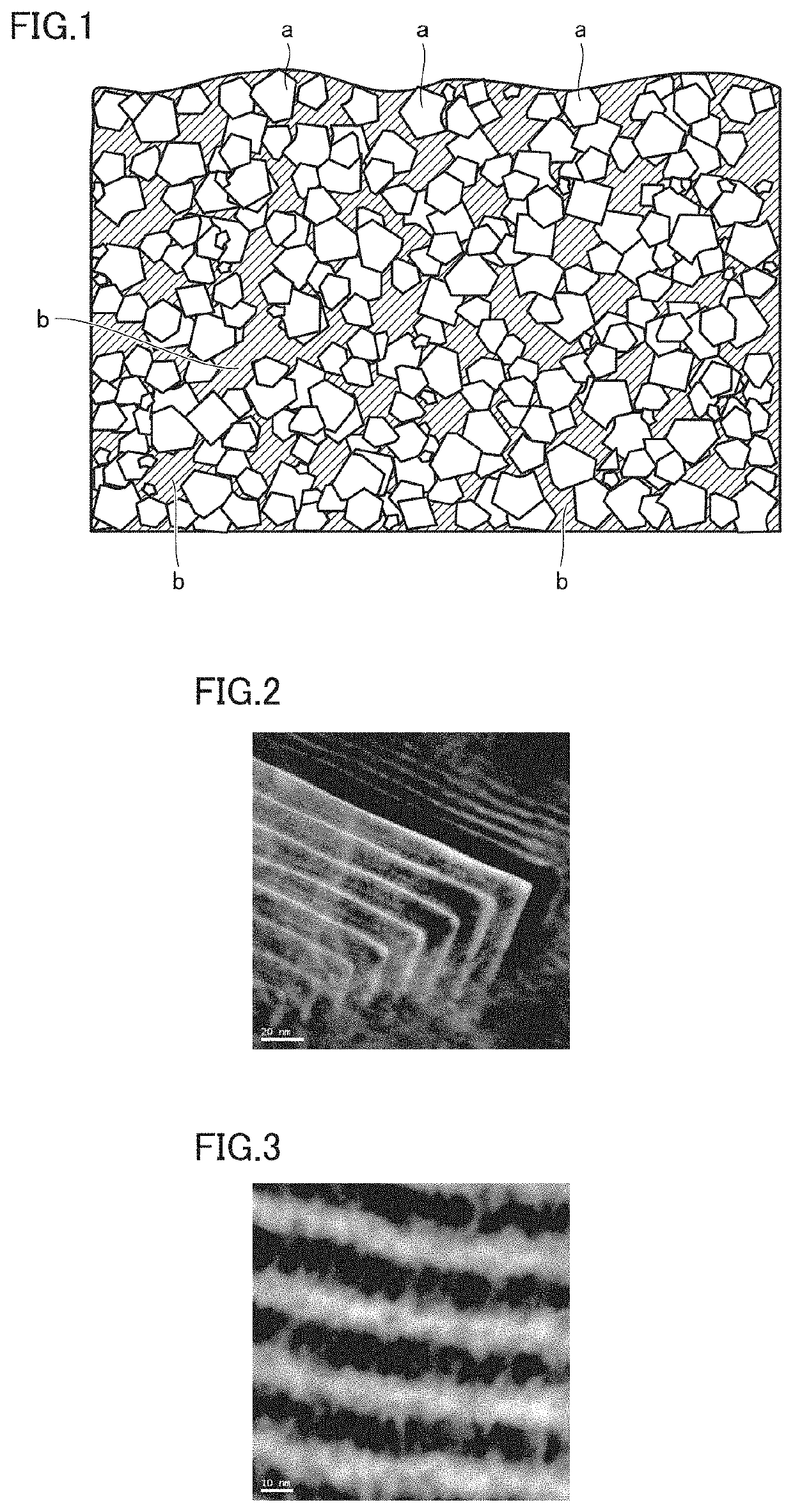
A surface-coated cutting tool includes a substrate and a coating film that coats the substrate, wherein the coating film includes a hard coating layer constituted of a domain region and a matrix region, the domain region is a region having a plurality of portions divided and distributed in the matrix region, the domain region has a structure in which a first layer composed of a first Alx1Ti(1-x1) compound and a second layer composed of a second Alx2Ti(1-x2) compound are layered on each other, the matrix region has a structure in which a third layer composed of a third Alx3Ti(1-x3) compound and a fourth layer composed of a fourth Alx4Ti(1-x4) compound are layered on each other.

Description

TECHNICAL FIELD[0001]The present disclosure relates to a surface-coated cutting tool and a method for manufacturing the surface-coated cutting tool. The present application claims a priority based on Japanese Patent Application No. 2018-054716 filed on Mar. 22, 2018, the entire content of which is incorporated herein by reference.BACKGROUND ART[0002]Conventionally, a cutting tool composed of cemented carbide has been used to cut steel, casting, or the like. During the cutting, the cutting edge of such a cutting tool is exposed to a severe environment such as high temperature and high stress, thus resulting in wear and breakage of the cutting edge.[0003]Therefore, in order to improve the life of the cutting tool, it is important to suppress the wear and breakage of the cutting edge.[0004]In order to improve cutting performance of the cutting tool, coating films, each of which coats a surface of a substrate composed of cemented carbide or the like, have been developed. Among them, a c...

Claims


Application Information

Patent Timeline
Patent Type & Authority Patents(United States)
IPC IPC(8): B23B27/14C23C16/34C23C16/36C23C16/455C23C28/04B23C5/16
CPCC23C16/342B23B27/14B23C5/16C23C16/36C23C16/45559C23C28/044Y10T407/00Y10T428/12007C23C16/34C23C30/005C23C28/40C23C28/42C23C28/042C23C28/04C23C16/45512C23C16/45578B23B51/00B23D77/00B23F21/00B23G5/06B23P15/28C23C16/38
Inventor KIDO, YASUKIPASEUTH, ANONGSACKOKUNO, SUSUMUIMAMURA, SHINYA
Owner SUMITOMO ELECTRIC HARDMETAL CORP
Why Eureka
Try Eureka