Light emitting device

a technology of light-emitting devices and light-emitting tubes, which is applied in the field of light-emitting devices, can solve the problems of skin infections caused by bacteria resistant to antibiotics, skin infections caused by bacteria frequently occurring, and become major problems, and achieve the effect of convenient portability

Active Publication Date: 2022-05-17
SEOUL VIOSYS CO LTD
View PDF11 Cites 0 Cited by
  • Summary
  • Abstract
  • Description
  • Claims
  • Application Information

AI Technical Summary

Benefits of technology

[0006]Embodiments of the present disclosure provide a light emitting device capable of curing skin infected with bacteria. Embodiments of the present disclosure provide a light emitting device for skin care, which is easy to carry and can be used even during users' activity. Embodiments of the present disclosure provide a light emitting device capable of curing not only bacterial infections but also various diseases.
[0008]According to embodiments of the present disclosure, the light emitting device can cure the skin through sterilization of a region of the skin infected by bacteria using UV light having a sterilization function. According to embodiments of the present disclosure, the light emitting device is easy to carry and can be used in user activity. According to embodiments of the present disclosure, the light emitting device can be used not only for sterilization of bacteria but also for curing other types of diseases.

Problems solved by technology

Skin infections caused by bacteria resistant to antibiotics, such as MRSA (Methicillin-resistant Staphylococcus aureus) and VRE (Vancomycin Resistant Enterococcus), are becoming major issues.
In addition, skin infections caused by bacteria frequently occur after surgery or in diabetic patients.
Infections caused not only by bacteria resistant to antibiotics but also by other bacteria are fatal to patients with low immunity or to the old and weak.
However, skin infections caused by bacteria resistant to the antibiotics can be cured only with a limited kind of antibiotics.
Moreover, treatment of the skin infections with the antibiotics requires a long period of time and entails side effects, high costs and stress on the patients.

Method used


Image

  • Light emitting device
  • Light emitting device
  • Light emitting device

Examples


ninth embodiment

[0084]FIG. 13 and FIG. 14 are exemplary views of a light emitting device according to the present disclosure. A light emitting device 900 includes a device housing 810 and a sterilization module 820. Referring to FIG. 13, the device housing 810 includes a sterilization module insertion portion 811 and a hanging portion 910. The sterilization module insertion portion 811 is formed on an upper surface of the device housing 810 and has a penetration structure.

eighth embodiment

[0085]The hanging portion 910 protrudes from an inner side surface of the device housing 810. In addition, the hanging portion 910 is formed to have elasticity. The hanging portion 910 may have the same structure as the hanging portion 812 of the light emitting device 800 (see FIG. 11 and FIG. 12) according to the

[0086]According to this embodiment, the hanging portion 910 is composed of a plurality of layers. Referring to FIG. 13, the hanging portion 910 is composed of three layers. For convenience of description, the hanging portion 910 includes a first hanging portion 911, a second hanging portion 912, and a third hanging portion 913. The number of layers constituting the hanging portion 910 may be changed, as needed.

[0087]Referring to FIG. 14, the sterilization module 820 is inserted into the device housing 810 through the sterilization module insertion portion 811. Here, the sterilization module 820 may be inserted into the device housing 810 to reach a preset location therein. ...


PUM

PropertyMeasurementUnit
wavelength bandaaaaaaaaaa
elasticityaaaaaaaaaa
areaaaaaaaaaaa

Abstract

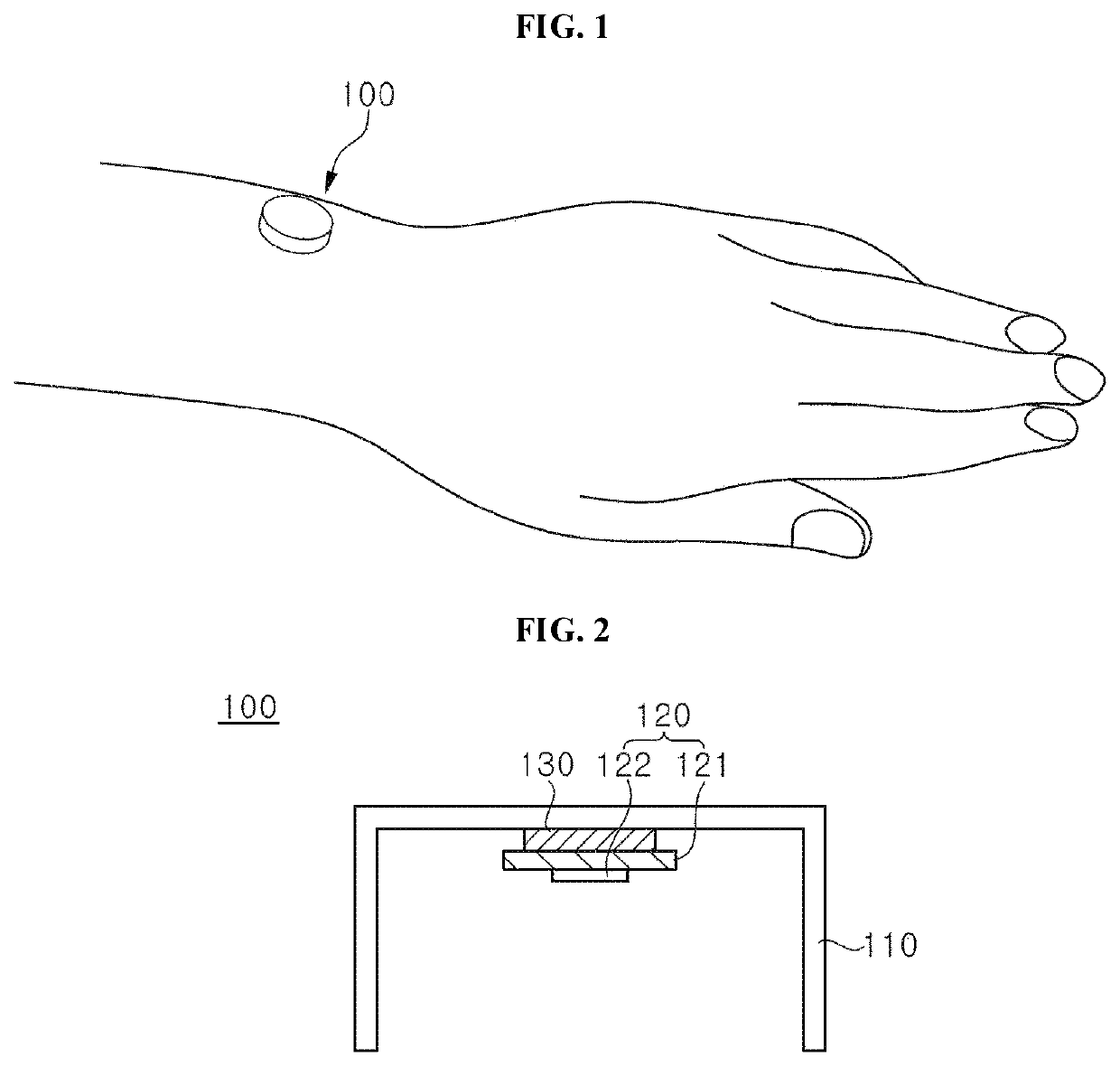
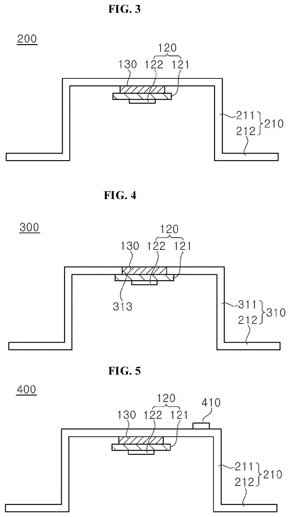
The present disclosure relates to a light emitting device. The light emitting device includes: a device housing having a structure with an open bottom; and a sterilization module installed in the device housing and emitting ultraviolet light for sterilization. Here, the sterilization module emits the ultraviolet light for sterilization to the open bottom of the device housing.

Description

CROSS-REFERENCE TO RELATED APPLICATION[0001]The present application is a continuation of PCT Application No. PCT / KR2018 / 006505 filed Jun. 8, 2018 which claims priority to Korean Patent Application No. 10-2017-0072648 filed Jun. 9, 2017 and entitled “Light Emitting Device,” the disclosures of which are hereby incorporated in its entirety by reference as set forth herein.TECHNICAL FIELD[0002]Embodiments of the present disclosure relate to a light emitting device.BACKGROUND ART[0003]Skin infections caused by bacteria resistant to antibiotics, such as MRSA (Methicillin-resistant Staphylococcus aureus) and VRE (Vancomycin Resistant Enterococcus), are becoming major issues. In addition, skin infections caused by bacteria frequently occur after surgery or in diabetic patients. Infections caused not only by bacteria resistant to antibiotics but also by other bacteria are fatal to patients with low immunity or to the old and weak.[0004]Skin infections caused by bacteria are generally cured w...

Claims


Application Information

Patent Timeline
Patent Type & Authority Patents(United States)
IPC IPC(8): A61L2/00A61L2/26A61N5/06
CPCA61L2/0047A61L2/26A61N5/0616A61N5/0624A61L2202/11A61N2005/0645A61N2005/0661A61L2/10A61N2005/0632A61L2202/24A61N2005/0643
Inventor JUNG, SANG WOOKBAE, HEE HO
Owner SEOUL VIOSYS CO LTD
Why Eureka
Try Eureka