Optically powered cryogenic focal plane array (FPA) with an optical data link

a cryogenic and optical data technology, applied in the field of cryogenic focal plane arrays, can solve the problems of limited thermal mass, limited physical contact with outside environments, increased thermal losses, etc., and achieve the effect of reducing electromagnetic interference in the cold volume and reducing heat leakage into the cold volum

Active Publication Date: 2022-05-17
RAYTHEON CO
View PDF9 Cites 2 Cited by
  • Summary
  • Abstract
  • Description
  • Claims
  • Application Information

AI Technical Summary

Benefits of technology

[0012]The present invention provides power to a cryogenic FPA with an optical data link optically thereby eliminating electrical penetrations of the cryogenic chamber for power delivery and further reducing heat leaks into the cold volume by copper wires and reducing electromagnetic interference in the cold volume.

Problems solved by technology

This volume is typically isolated from the rest of the system and has limited thermal mass, and limited physical contact with outside environments.
Electrical lines are very good thermal conductors that provide paths for heat leakage into the cryogenic volume, which can be a problem for systems with multiple inputs / outputs.
The electrical lines are also a source of electromagnetic interference (EMI) near the cryogenic area.
As data transfer rates increase, the number of electrical lines, hence thermal losses will increase.
As data rates and sensor sizes increase, it is not feasible to continue to add additional electronic data transmission lines, as it would require a cooling system whose capacity / size / weight would not be compatible with overall system requirements.

Method used


Image

  • Optically powered cryogenic focal plane array (FPA) with an optical data link
  • Optically powered cryogenic focal plane array (FPA) with an optical data link
  • Optically powered cryogenic focal plane array (FPA) with an optical data link

Examples


Embodiment Construction

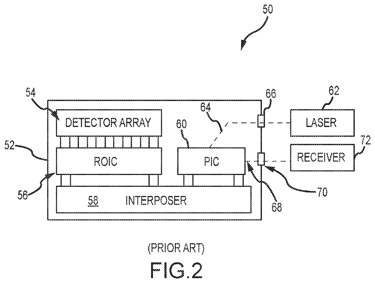
[0027]The conventional all-electrical cryogenic FPA has a single penetration (best case) to bring power to the chamber and provide data transfer. That single penetration may be a large electrical connector that suffers from heat leakage and EMI. AIM Photonic's architecture for a cryogenic FPA with a PIC increases the data transfer rates out of the ROIC and reduces heat leakage into the cold volume by copper wires and EMI. However, the proposed architecture does not eliminate electrical penetrations of the chamber. Power is brought into the chamber via electrical wires for various DC+, DC−, and ground signals. Furthermore, the thermocouple measurement is brought out of the chamber via an electrical wire. These remaining electrical penetrations provide paths for leaking heat and providing EMI. Best case, the AIM photonics architecture has two penetrations of the chamber; one electrical and one optical. In addition, the proposed architecture does not address how to bring data into the ...


PUM

PropertyMeasurementUnit
optical poweraaaaaaaaaa
electrical poweraaaaaaaaaa
DC voltageaaaaaaaaaa

Abstract

An optically powered cryogenic FPA with an optical data link eliminates electrical penetrations of the cryogenic chamber for power delivery thereby reducing heat leaks into the cold volume by copper wires and EMI. An optical splitter receives and separates an optical input signal into an optical carrier signal, an optical Data IN signal and an optical power signal. An optical-to-electrical (O / E) converter converts the optical power signal into an electrical power signal, which is converted into a plurality of DC voltage signals to supply power within the chamber. An optical data link modulates the optical carrier signal with electrical signals from the ROIC to form and output an optical Data OUT signal.

Description

BACKGROUND OF THE INVENTIONField of the Invention[0001]This invention relates to cryogenic focal plane arrays (FPAs), and more particularly to an optically powered cryogenic focal plane array (FPA) with an optical data link.Description of the Related Art[0002]Many optical systems employ focal plane arrays (FPAs), which typically include an optical detector array (ODA) and a read out integrated circuit (ROIC), to sense image information. One important class of FPAs are infrared sensing arrays. Such arrays are useful for image detection and motion sensing.[0003]All objects, including the components of the FPA system, give off infrared radiation whose intensity is proportional to their temperature. In order maximize system sensitivity and minimize noise, thereby maximizing signal-to-noise ratio (SNR), it is common to cool infrared sensing FPAs to cryogenic temperatures to minimize system-induced noise in detected images and to prevent system component emissions from swamping desired lo...

Claims


Application Information

Patent Timeline
Patent Type & Authority Patents(United States)
IPC IPC(8): G01J5/06G02B13/14H04B10/80H04B10/516G02B27/10F25D19/00G01J5/061F25B9/14G01J5/0806
CPCG01J5/061F25B9/14G01J5/0806G02B13/14G02B27/1006H04B10/516H04B10/807F25D19/00G01J5/0821G01J5/045G01J5/14G01J5/025G01J2005/0077
Inventor UYENO, GERALD P.KELLER, SEAN D.GLEASON, BENN
Owner RAYTHEON CO
Why Eureka
Try Eureka