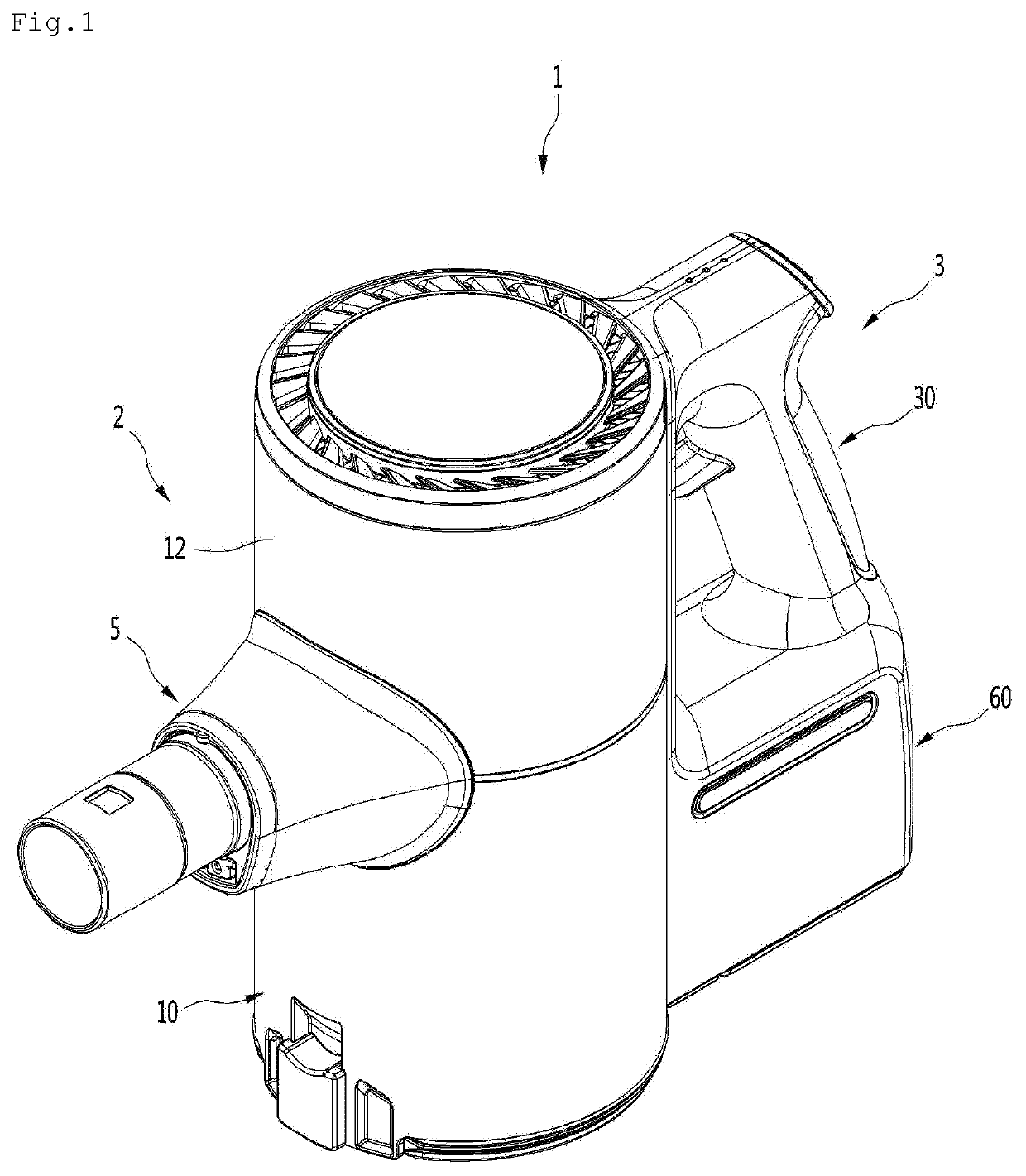
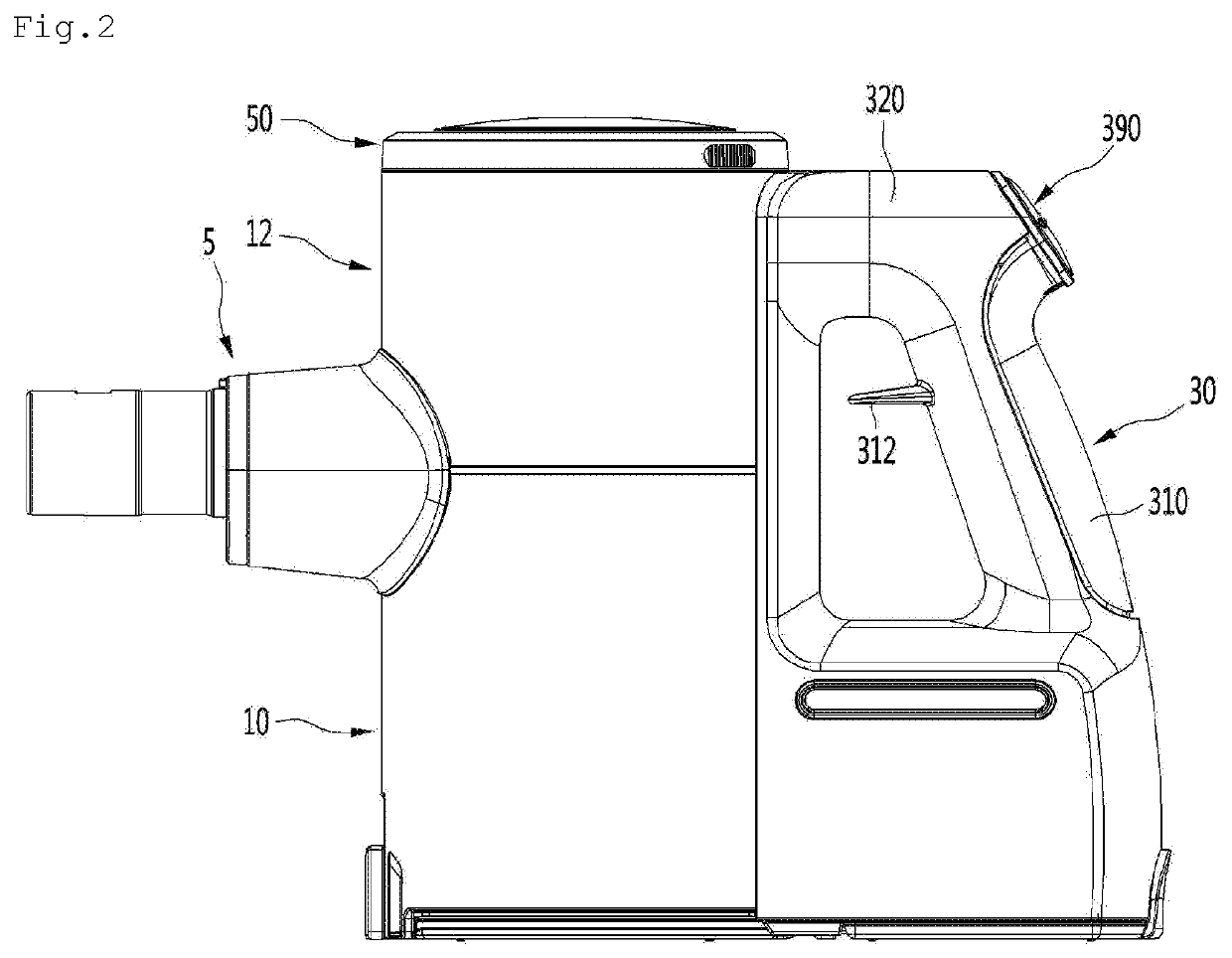
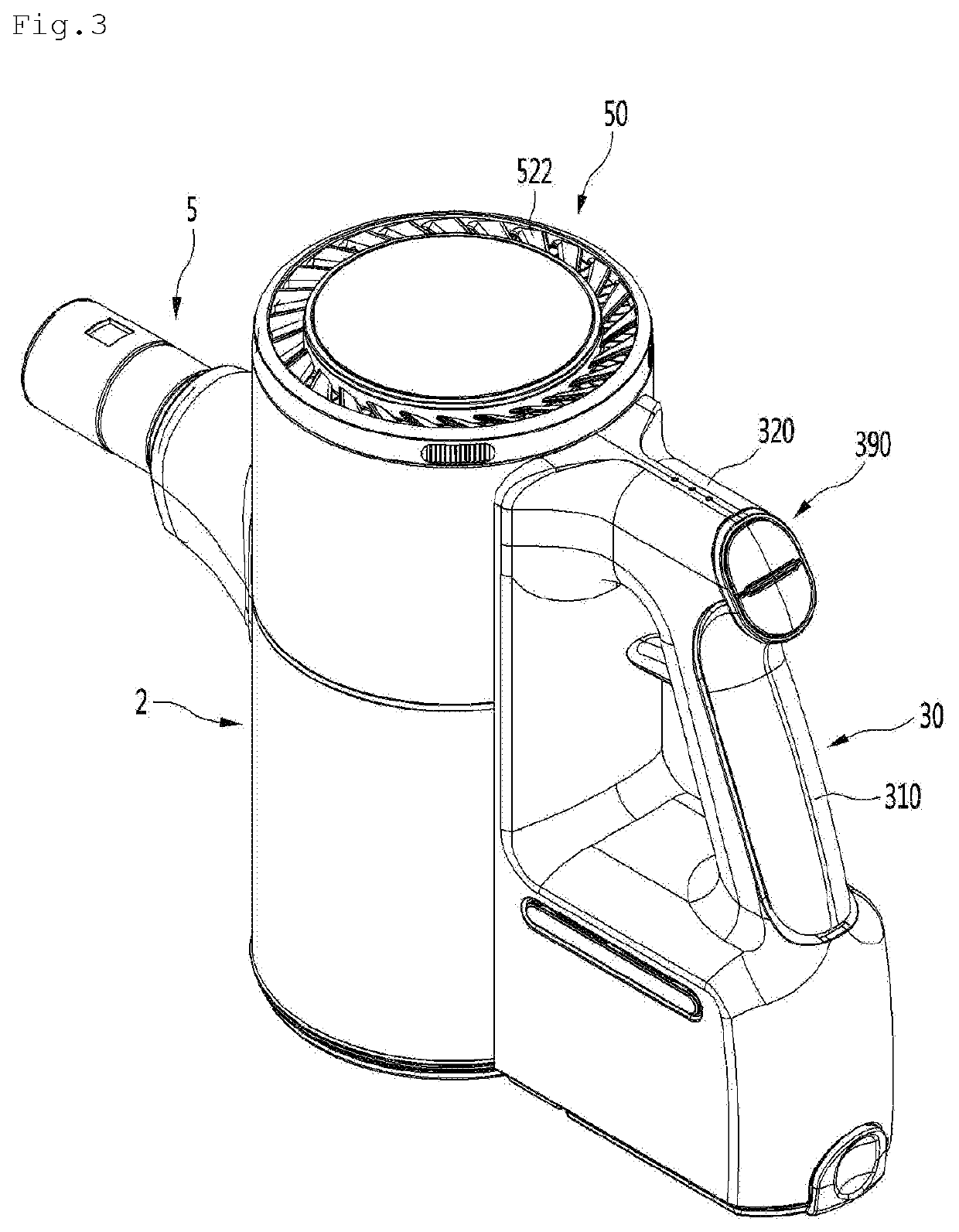
Vacuum cleaner

a vacuum cleaner and vacuum technology, applied in the field of vacuum cleaners, can solve the problems of difficult installation small internal space of the handle, complicated structure of the vacuum cleaner, etc., and achieve the effects of improving the connection reducing the size of the main vacuum cleaner, and improving the coupling accuracy between the main vacuum cleaner and the connector

Active Publication Date: 2022-05-31
LG ELECTRONICS INC
View PDF20 Cites 0 Cited by
  • Summary
  • Abstract
  • Description
  • Claims
  • Application Information

AI Technical Summary

Benefits of technology

[0032]According to the proposed invention, since the main PCB includes the slit, and the slit insertion protrusion is formed on the connector, the coupling accuracy between the main PCB and the connector may be improved.
[0033]Also, since the connector includes the two connecting bodies, the main PCB is inserted into the PCB receiving space between the two connecting bodies, and the slit insertion protrusion is accommodated in the slit of the main PCB, the additional fixing unit such as the hook for fixing the main PCB to the connector may be unnecessary.
[0034]Also, while the handle part is slid with respect to the main body, since the main PCB is connected to the connector, the process of connecting the main PCB to the connector may be unnecessary.
[0035]Also, since the pad is provided on each of both surfaces of one PCB constituting the main PCB, and the one PCB is inserted between the two connecting bodies, the signal may be transmitted as long as one pad of the pads on both surfaces of the one PCB is connected to the connecting pin, and thus, the connection accuracy between the main PCB and the connector may be improved.
[0036]Also, since the main PCB is divided into the two PCBs and inserted in handle body, the size of the main PCB may be reduced.
[0037]Also, in the process of inserting the main PCB assembly into the accommodation space of the handle body in the state in which the two PCBs are connected to the PCB connector, the main PCB assembly may be coupled to the handle body. Therefore, the structure for fixing the two PCBs to each other and the structure for fixing the two PCBs to the handle body may be simplified, and the assembling process of the user may be easy.

Problems solved by technology

According to the document, however, the airflow generator is disposed over the handle and the power supply is disposed under the handle, so the internal space of the handle is small.
Therefore, the structure for installing the PCB is complicated and it is difficult to install the PCB.

Method used


Image

  • Vacuum cleaner
  • Vacuum cleaner
  • Vacuum cleaner

Examples


Embodiment Construction

[0059]Hereinafter, some embodiments of the present disclosure will be described in detail with reference to the accompanying drawings. It should be noted that when components in the drawings are designated by reference numerals, the same components have the same reference numerals as far as possible even though the components are illustrated in different drawings. Further, in description of embodiments of the present disclosure, when it is determined that detailed descriptions of well-known configurations or functions disturb understanding of the embodiments of the present disclosure, the detailed descriptions will be omitted.

[0060]Also, in the description of the embodiments of the present disclosure, the terms such as first, second, A, B, (a) and (b) may be used. Each of the terms is merely used to distinguish the corresponding component from other components, and does not delimit an essence, an order or a sequence of the corresponding component. It should be understood that when o...


PUM


Abstract

A vacuum cleaner of the present invention comprises: a main body having a suction motor for generating suction force; a main PCB capable of generating a control command for the suction motor; a handle part capable of accommodating the main body PCB; and a connector provided at the main body, and to which the main PCB is connected in a process of coupling the handle part to the main body. The main PCB includes a plurality of pads and a slit, and the connector includes: a plurality of connecting pins for making contact with the plurality of pads; and a slit insertion protrusion inserted into the slit.

Description

CROSS-REFERENCE TO RELATED APPLICATIONS[0001]This application is a National Stage application under 35 U.S.C. § 371 of International Application No. PCT / KR2017 / 009062, filed on Aug. 18, 2017, which claims the benefit of Application No. 10-2016-0183824, filed on Dec. 30, 2016 and Application No. 10-2016-0177827, filed on Dec. 23, 2016, and Application No. 10-2016-0108319, filed on Aug. 25, 2016. The disclosures of the prior applications are incorporated by reference in their entirety.TECHNICAL FIELD[0002]The present invention relates to a cleaner.BACKGROUND ART[0003]Cleaners are devices that suctions or washes dusts or foreign substances to be cleaned so as to perform cleaning.[0004]Cleaners may be classified into a manual cleaner that a user moves in person for cleaning and an automatic cleaner that automatically moves for cleaning.[0005]Manual cleaners may fall into, depending on the types, a canister cleaner, an upright cleaner, a handy cleaner, and a stick cleaner.[0006]Meanwhile...

Claims


Application Information

Patent Timeline
Patent Type & Authority Patents(United States)
IPC IPC(8): A47L9/32A47L5/24A47L9/28H05K5/00H05K1/11H01R33/76H01R33/955A47L9/22A47L9/16H02J7/00A47L9/12H01R12/70H01R12/72
CPCA47L9/322A47L5/24A47L9/122A47L9/1683A47L9/22A47L9/28A47L9/2857A47L9/2884A47L9/2894H01R33/7671H01R33/955H02J7/0045H05K1/111H05K5/003H05K5/0069H01R12/7088H01R12/721H05K2201/09027H05K2201/09063H05K2201/10106
Inventor LEE, CHANGJUNHWANG, PHILJAEHWANG, MANTAEHWANG, JUNGBAESUNG, EUNJILEE, TAEKGI
Owner LG ELECTRONICS INC
Why Eureka
Try Eureka