Packaging equipment and method for polarization maintaining fiber butterfly laser

A technology for packaging equipment and lasers, which is applied in the direction of laser welding equipment, lasers, laser components, etc., can solve problems such as cumbersome operations, achieve high monitoring accuracy, simplify the packaging process, and achieve the effects of small deformation of weldments

Active Publication Date: 2021-08-03
CENT SOUTH UNIV
View PDF24 Cites 0 Cited by
  • Summary
  • Abstract
  • Description
  • Claims
  • Application Information

AI Technical Summary

Problems solved by technology

In the above solution, the front end of the fiber is fixed on the heat sink by a saddle clamp, and the operation is relatively cumbersome. At the same time, it is difficult to realize the welding between the end of the fiber and the through hole by relying on the laser welding device above. Therefore, there is still room for further optimization of the packaging method of the butterfly laser.

Method used


Image

  • Packaging equipment and method for polarization maintaining fiber butterfly laser
  • Packaging equipment and method for polarization maintaining fiber butterfly laser
  • Packaging equipment and method for polarization maintaining fiber butterfly laser

Examples


Embodiment 1

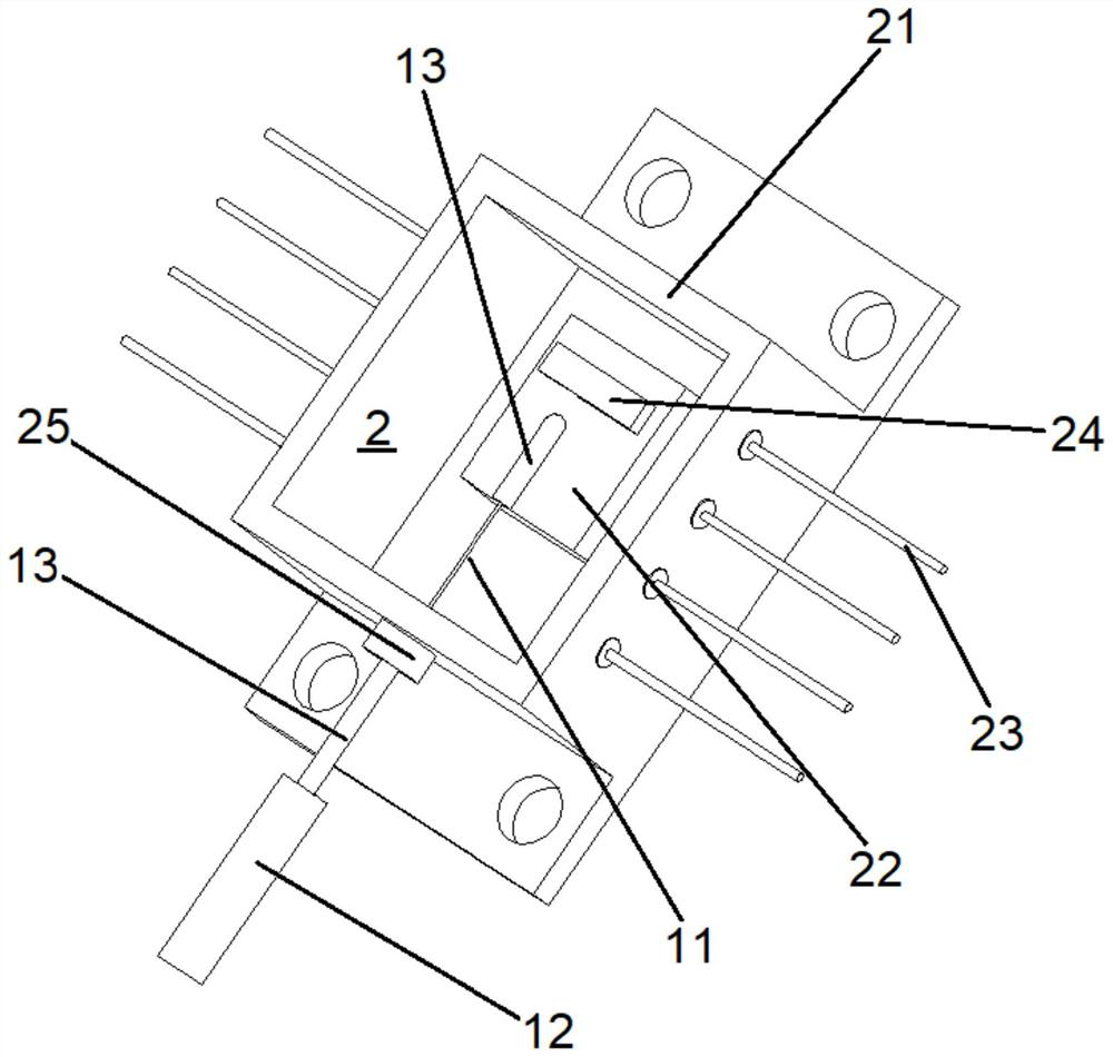
[0043] In this embodiment, the optical fiber 1 is a polarization-maintaining optical fiber, including a fiber front end 11 and a fiber tail end 12. The diameter of the fiber tail end 12 is enlarged relative to the fiber front end 11, and a metal Casing 13. The tube case 2 is butterfly-shaped and includes a bottom plate, a box body 21 arranged on the bottom plate, a heat sink 22 arranged in the box body 21 and pins 23 for power-on arranged on both sides of the box body 21. 22 is provided with a chip 24 . When packaging, the fiber front end 11 and the metal sleeve 13 here are sent to the upper surface of the heat sink 22 from the through hole 25 on one side of the box body 21 to complete the optical power and angle coupling between the optical fiber 1 and the chip 24, and then the fiber front end The metal sleeve 13 of 11 is welded to the heat sink 22, the metal sleeve 13 of the fiber end 12 is welded to the side wall of the through hole 25, and the butterfly laser as a whole c...

Embodiment 2

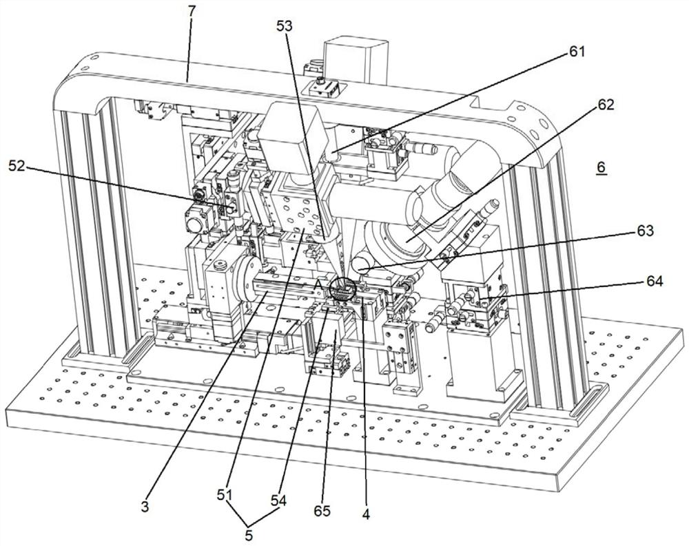
[0056] Embodiment 2 of the present invention provides a packaging method for a polarization-maintaining fiber butterfly laser, which can be referred to at the same time Figure 9 , including the following steps:

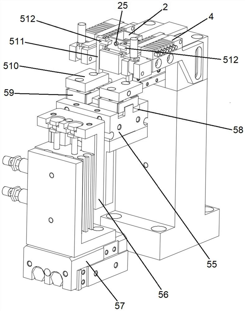
[0057] Step 1, place the shell 2 of the butterfly laser on the shell fixture module 4 to clamp and fix it, and power on the butterfly laser through the contact between the leads 46 on both sides and the pins 23, so that the chip 24 of the butterfly laser emits light , to perform optical power coupling and polarization extinction ratio (angle) coupling;

[0058] Step 2, place the optical fiber 1 on the optical fiber end clamp 35, control the optical fiber end clamp 35 so that the optical fiber 1 enters the interior of the tubular shell 2 from the through hole 25 of the tubular shell 2, and ensure that the optical fiber 1 and the metal sleeve 13 are as far as possible during this process etc. are coaxial with the through hole 25;

[0059] Step 3, when the visual moni...


PUM


Abstract

The invention provides a packaging device for a polarization-maintaining optical fiber butterfly laser, which includes an optical fiber clamp module, a shell clamp module, a welding module and a visual monitoring module. The optical fiber clamp module clamps the optical fiber and sends it into the shell, adjust The position and angle of the optical fiber are coupled, the shell fixture module clamps and positions the shell, and can power on the shell, the welding module welds the metal sleeve on the coupled optical fiber in the shell, and is used for the visual monitoring module For monitoring the position and angle of the optical fiber; the welding module includes a tail pipe welding assembly arranged on one side of the shell fixture module, on which at least two electrodes are arranged, which can contact and conduct electricity on both sides of the through hole of the shell. The structure design of each module in the present invention is reasonable, and the connection and cooperation are compact, which simplifies the packaging process and improves the production efficiency. At the same time, it solves the problem that it is difficult to weld the metal sleeve at the tail end by using laser welding components, and has the advantages of small deformation of welding parts and easy realization of automatic control. The advantages.

Description

technical field [0001] The invention relates to the technical field of butterfly laser packaging, in particular to a packaging device and method for a polarization-maintaining fiber butterfly laser. Background technique [0002] The light emitted by semiconductor lasers for communication is linearly polarized light. When it is transmitted in a common single-mode fiber, if the fiber is bent or twisted, the polarization state of the optical signal will change. The polarization state of the optical signal is an important optical characteristic. In many applications, there are clear requirements for the polarization state of the optical signal, and a polarization-dependent light source is required. Therefore, it is necessary to directly couple the light emitted by the laser chip into the polarization-maintaining fiber for further processing. use. [0003] Polarization-maintaining fiber is a kind of fiber that transmits linearly polarized light. The use of polarization-maintaini...

Claims


Application Information

Patent Timeline
Patent Type & Authority Patents(China)
IPC IPC(8): H01S3/067B23K37/04B23K26/70B23K26/346B23K26/08
CPCB23K26/0853B23K37/0435B23K26/346B23K26/702H01S3/06704H01S3/06712
Inventor 段吉安彭晋文卢胜强徐聪唐佳
Owner CENT SOUTH UNIV
Why Eureka
Try Eureka