Unlock instant, AI-driven research and patent intelligence for your innovation.

Cooling system and cooling method

Active Publication Date: 2022-05-31
MAZDA MOTOR CORP
View PDF13 Cites 0 Cited by
  • Summary
  • Abstract
  • Description
  • Claims
  • Application Information

AI Technical Summary

Benefits of technology

The present disclosure provides a cooling system and method for preventing an engine from overheating when a grille shutter is in an abnormal state. The system includes a cooling water passage through which cooling water is supplied to a water jacket in the engine, a radiator, and a grille shutter. The controller detects abnormalities in the grille shutter and controls the flow rate adjuster to increase the flow rate of the cooling water supplied to the undercover cooling water passage. This prevents overheating of the engine and ensures efficient cooling. The cooling system also includes a bypass passage and a valve to adjust the flow rate of the cooling water. The method includes determining the abnormality of the grille shutter and increasing the flow rate of the cooling water supplied to the undercover cooling water passage.

Problems solved by technology

Thus, even when an airflow into the engine bay from the grille becomes difficult due to the abnormality of the grille shutter and the cooling water cannot be efficiently cooled in the radiator, the cooling of the cooling water in the undercover cooling water passage is stimulated.

Method used


Image

  • Cooling system and cooling method
  • Cooling system and cooling method
  • Cooling system and cooling method

Examples


first embodiment

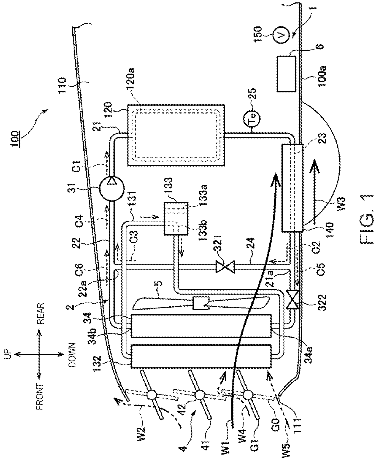
[0018]First, a vehicle 100 equipped with the cooling system 1 according to the first embodiment will be described with reference to FIG. 1. FIG. 1 is a schematic view of the vehicle 100 on which the cooling system 1 is mounted. An engine bay 110 accommodating an engine 120 is formed in a front part of the vehicle 100. An undercover 140 is disposed below the engine 120. The undercover 140 is made of a metal material having a high thermal conductivity (e.g., aluminum). The undercover 140 covers a lower part of the engine bay 110 and forms at least a part of a bottom surface 100a of the vehicle 100.

[0019]Here, a direction to which the vehicle 100 travels forward is referred to as “front” and a direction to which the vehicle 100 travels backward is referred to as “rear.” Moreover, a vertically upward direction is referred to as “up” and a vertically downward direction is referred to as “down.”

[0020]The vehicle 100 is mounted thereon with an air conditioner (not illustrated) which adjust...

second embodiment

[0075]Next, the cooling system 1A according to the second embodiment is described with reference to FIG. 5. The cooling system 1A cools air used in an exhaust gas recirculation (EGR) system 8 mounted on a vehicle 100A in addition to the air used in the engine 120. Parts of a configuration of the cooling system 1A having the same components as those of the first embodiment are denoted with the same reference numerals, and the description thereof is suitably omitted. FIG. 5 is a schematic view of the vehicle 100A on which the cooling system 1A is mounted.

[0076]The EGR system 8 is mounted on the vehicle 100A in order to prevent generation of nitrogen oxides in the engine 120 and knocking. The EGR system 8 includes an EGR gas passage 81, an EGR cooler 82, and an EGR valve 83.

[0077]The EGR gas passage 81 connects an exhaust duct 121 and an intake duct 123. High-temperature gas discharged from the engine 120 to the exhaust duct 121 partially flows through the EGR gas passage 81 and is gui...


PUM


Abstract

A cooling system configured to cool an engine of a vehicle is provided, which includes a cooling water passage through which cooling water is supplied to a water jacket in the engine, and having an undercover cooling water passage provided in an undercover and where the cooling water is cooled by exchanging heat with air below the undercover, a radiator provided in the cooling water passage and configured to cool the cooling water by exchanging heat with air flowing into an engine bay from a grille, a flow rate adjuster, a grille shutter provided to the grille and configured to change an effective opening area of the grille, and a controller configured to determine abnormality of the grille shutter and control, when determined as abnormal, the flow rate adjuster to increase the flow rate of the cooling water supplied to the undercover cooling water passage.

Description

TECHNICAL FIELD[0001]The present disclosure relates to a cooling system which cools an engine of a vehicle, and a method of cooling an engine of a vehicle.BACKGROUND OF THE DISCLOSURE[0002]Air flows into an engine bay from a grille of a vehicle as the vehicle travels. Although this air can be used to cool cooling water in a radiator, it acts as resistance in traveling of the vehicle and fuel efficiency degrades. For example, JP2015-223905A discloses a grille shutter provided to a grille of a vehicle. When a given condition is met, the grille shutter closes the grille to prevent air from flowing therein and reduce air resistance to the vehicle.[0003]The grille shutter of JP2015-223905A may disturb the vehicle traveling when an abnormality occurs in the grille shutter. For example, in a case where the grille shutter is in an abnormal state and cannot open the grille, the cooling of the cooling water in the radiator becomes difficult and the engine may overheat.SUMMARY OF THE DISCLOSUR...

Claims


Application Information

Patent Timeline
Patent Type & Authority Patents(United States)
IPC IPC(8): F01P7/10F01P3/20F01P11/10B60K11/02F02F1/16F01P7/14F01P5/10G07C5/08
CPCF01P7/10F01P5/10F01P7/14F02F1/16G07C5/0808F01P2007/146F01P2025/66F01P3/18F01P2003/185F01P2003/187G07C5/0825Y02T10/88
Inventor YAMAGA, YUMAKOIKE, YUSUKETANEHIRA, TAKAFUMIYAMAGUCHI, KANICHITANINAKA, KATSUTOSHIMIKUNI, YUSUKEMARUTANI, YUSUKE
Owner MAZDA MOTOR CORP