
Positive polymer fecal sludge treatment apparatus

a polymer fecal sludge and treatment apparatus technology, applied in the direction of biological sludge treatment, water treatment parameter control, treatment water, etc., can solve the problems of reducing treatment efficiency and longer treatment time, and achieve fast, high-efficiency and uninterrupted operation, the effect of cleaner water discharg

Active Publication Date: 2022-06-14
LIN FRANK
View PDF5 Cites 0 Cited by
  • Summary
  • Abstract
  • Description
  • Claims
  • Application Information

AI Technical Summary

Benefits of technology

[0003]In order to improve the conventional fecal sludge treatment system, the present invention provides a positive polymer fecal sludge treatment apparatus with high efficiency and high speed.
[0005]A positive polymer fecal sludge treatment apparatus includes a trash separator, one end of the trash separator is connected with a sludge inlet and the other end of the trash separator is connected with a twin-rotor vacuum water pump, a high-pressure transparent tube is disposed and connected, by a knife valve, between the trash separator and the twin-rotor vacuum water pump, a plurality of knife valves are disposed, one end of the knife valve is connected with a first material box and a second material box, a first chemical box and a second chemical box are disposed under the first material box and the second material box, each of the first material box and the second material box is connected with the first chemical box and the second chemical box, the first material box and the second material box are also connected with a mixing box, one end of the mixing box is connected with the first chemical box, and the other end of the mixing box is connected with a multi-disk screw press and a wastewater outlet, and one end of the multi-disk screw press is connected with a sludge outlet. The first material box and the second material box have a larger volume than a conventional one and thus can store more material and also can perform chemical stirring reaction directly. The multi-disk screw press has a longer length and a longer dewatering working stroke so that the fecal sludge can be treated cleaner and drier. When the mixing box runs, if the fecal sludge is not separated thoroughly, a second addition of chemical can be made for further solid-liquid separation.
[0010]The present invention has the following beneficial effects: together with the two material boxes and two chemical boxes, the two large mixing boxes can work alternately to realize quick, high-efficiency and uninterrupted operation. The two chemical boxes included in each of the chemical boxes of different models can work alternately and uninterruptedly to realize double charging of type C chemical and type M chemical, thereby realizing faster chemical reaction and cleaner water discharge. Further, in cooperation with the numerical control operation box, timed charging can be performed in a given amount. The first material box and the second material box have a larger volume than a traditional one, can store more material and can perform chemical stirring reaction directly. The numerical control ball valve can control the discharge speed with each increase or decrease of 10%. The multi-disk screw press has a longer length and a longer dewatering working stroke so that the fecal sludge can be treated cleaner and drier. When the mixing box runs, if the fecal sludge is not separated thoroughly, a second addition of chemical can be made for further solid-liquid separation. By use of the numerical control operation box, full automatic operation can be realized, which is more advanced than a manual or semi-automatic operation. A manual valve is disposed at the position connecting the three-way valve with various components. When a component needs washing, the washing can be performed by opening a corresponding manual valve. Further, with the function of water suction and discharge, a large quantity of water can be sucked and discharged.

Problems solved by technology

However, the apparatus of the method occupies a larger area, has a demanding temperature requirement, and takes a longer time of treatment with a lower treatment efficiency.

Method used

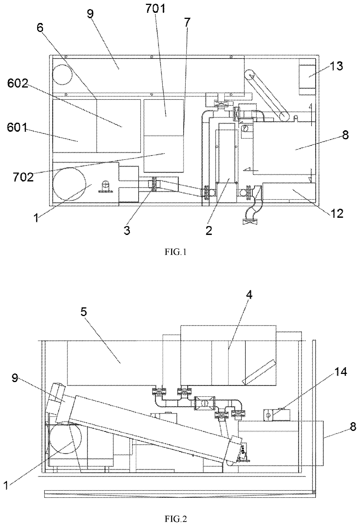
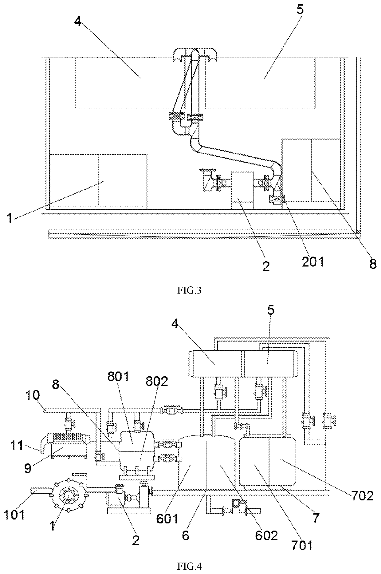

Image

  • Positive polymer fecal sludge treatment apparatus
  • Positive polymer fecal sludge treatment apparatus
  • Positive polymer fecal sludge treatment apparatus

Examples


Embodiment Construction

[0018]By detailing the non-limiting examples of the present disclosure in combination with the drawings below, other features, the object and the advantages of the present disclosure will become more apparent.

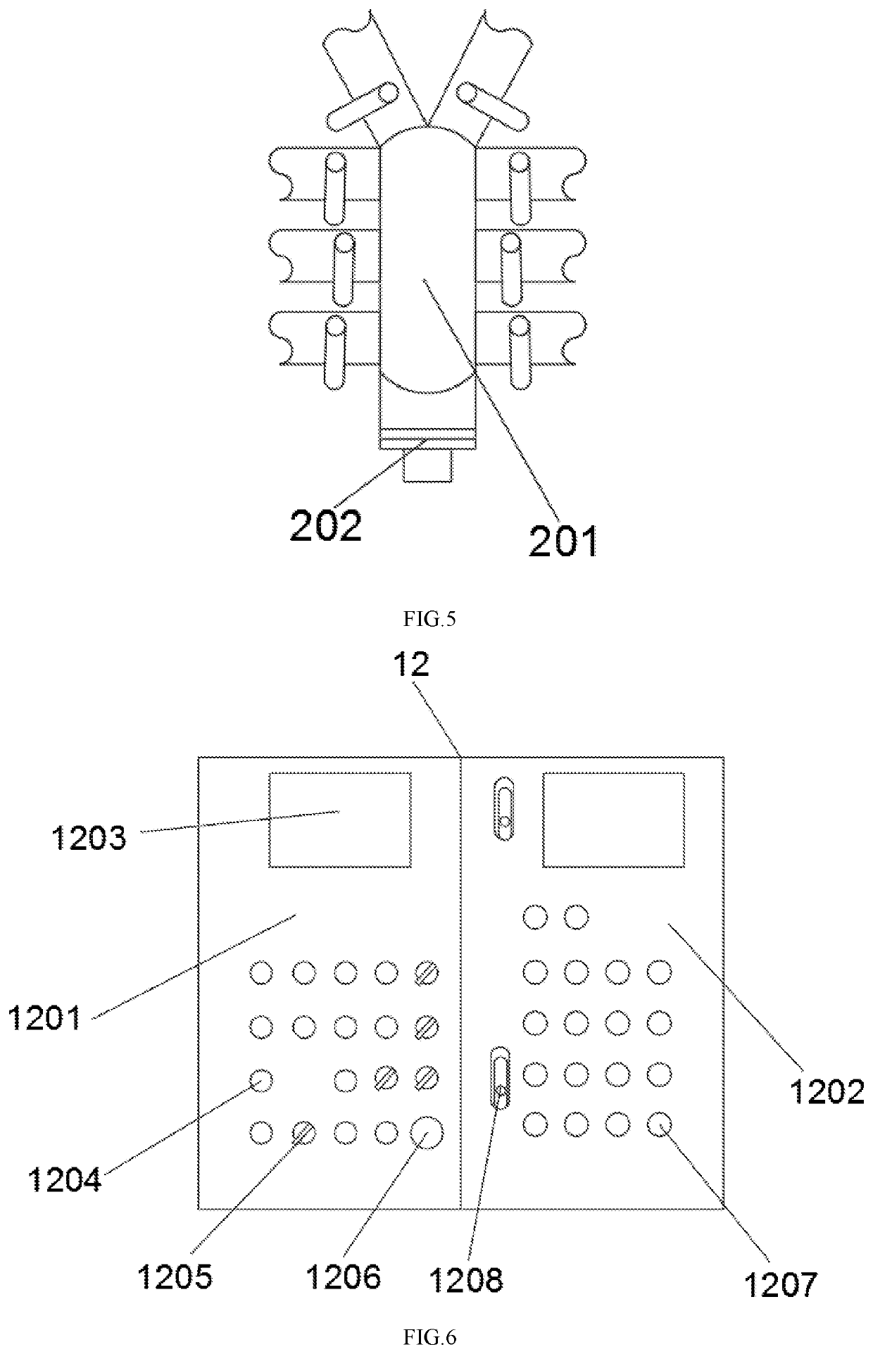
[0019]Numerals of drawings in FIGS. 1-7 are described as follows: trash separator 1, twin-rotor vacuum water pump 2, high-pressure transparent tube 3, first material box 4, second material box 5, first chemical box 6, second chemical box 7, mixing box 8, multi-disk screw press 9, wastewater outlet 10, sludge outlet 11, numerical control operation box 12, air compressor 13, mixer 14, sludge inlet 101, three-way valve 201, rotary valve 202, first left chemical box 601, first right chemical box 602, second left chemical box 701, second right chemical box 702, first mixing box 801, second mixing box 802, automatic control box 1201, pneumatic control box 1202, display screen 1203, indicator light 1204, rotary switch 1205, emergency stop button 1206, button switch 1207, box door swit...


PUM

PropertyMeasurementUnit
transparentaaaaaaaaaa
chemicalaaaaaaaaaa
concentrationaaaaaaaaaa

Abstract

A positive polymer fecal sludge treatment apparatus comprising a trash separator, one end of which is connected with a sludge inlet, and the other end of which is connected with a twin-rotor vacuum water pump. A high-pressure transparent tube is disposed and connected, by a knife valve, between the trash separator and the twin-rotor vacuum water pump. One end of the knife valve is connected with a first material box and a second material box. A first chemical box and a second chemical box are disposed under the first material box and the second material box, and each of the first material box and the second material box is connected with the first chemical box and the second chemical box. The first and second material boxes have a larger volume than a conventional one and thus can store more material and also can perform chemical stirring reaction directly.

Description

BACKGROUND OF THE INVENTION1. Field of the Invention[0001]The present invention belongs to the field of wastewater treatment technology and in particular relates to a positive polymer fecal sludge treatment apparatus.2. Description of the Related Art[0002]Fecal sludge refers to wastewater flushing feces of human during daily life, which is defined as domestic wastewater containing feces substances, for example, toilet wastewater and feces medium in toilets. The fecal sludge is a typical high-concentration organic wastewater for which the basic treatment task is to remove various organic matters therein. The current fecal sludge treatment method is a biological treatment method by which those organic matters in dissolved or colloidal state in the sludge are degraded by vital activities of microorganisms so as to purify the sludge. However, the apparatus of the method occupies a larger area, has a demanding temperature requirement, and takes a longer time of treatment with a lower tre...

Claims


Application Information

Patent Timeline
Patent Type & Authority Patents(United States)
IPC IPC(8): C02F11/02C02F103/00
CPCC02F11/02C02F2103/005C02F2201/005C02F2209/005C02F11/125C02F2303/24C02F11/147
Inventor LIN, YONGZHU
Owner LIN FRANK
Learn More