Methods and device for controlled cell stretch and imaging

a controlled cell and imaging technology, applied in measurement devices, scientific instruments, instruments, etc., can solve problems such as dna damage increase, and achieve the effect of dna damage increas

Active Publication Date: 2022-06-14
UNIV OF COLORADO THE REGENTS OF
View PDF8 Cites 0 Cited by
  • Summary
  • Abstract
  • Description
  • Claims
  • Application Information

AI Technical Summary

Benefits of technology

[0007]A low-cost, magnetically-driven device that enables visualization and quantification of dynamic changes in cell behavior during mechanical stretch. Using this device, we observed that nuclei of mouse embryonic skin fibroblasts underwent rapid but divergent responses to strain magnitude, showing nuclear area increase and chromatin decompaction during 5% (low) strain, but nuclear area decrease and chromatin condensation during 20% (high) strain. Only resp...

Problems solved by technology

Only responses to low strain were dependent on calcium, while actin inhi...

Method used


Image

  • Methods and device for controlled cell stretch and imaging
  • Methods and device for controlled cell stretch and imaging
  • Methods and device for controlled cell stretch and imaging

Examples


example 1

tch Device—Fabrication

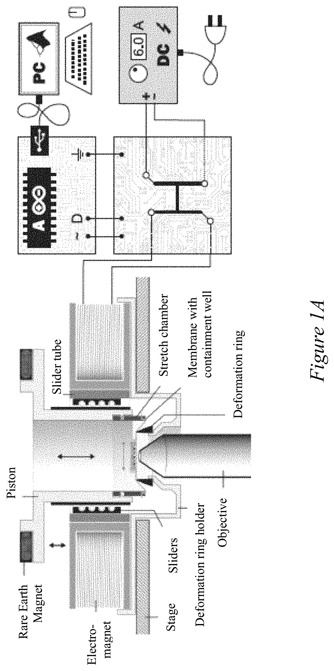
[0046]A cell stretch device was designed to acquire high-magnification images of cells during the application of equiaxial strain while also avoiding the use of expensive materials or complex designs. Two types of three-dimensional (3D) printers were used to fabricate a majority of the components: Objet30 (Computer Aided Technology, Buffalo Grove, Ill.), using the material VeroClear (OBJ-04055; Computer Aided Technology), and the uPrint SE Plus (311-20200; Computer Aided Technology), using ABS+. Designs for the device components were created as CAD files using SolidWorks (v. 2018; Dassault Systèmes SolidWorks). All parts were printed at the Integrated Teaching and Learning Laboratory at the University of Colorado Boulder.

[0047]The main body consisted of four parts: a deformation ring holder, an electromagnet case, a slider tube, and a piston (FIG. 1), which were printed using the uPrint SE Plus. The deformation ring holder was designed to fit into the circular ...

example 2

tch Device—Control

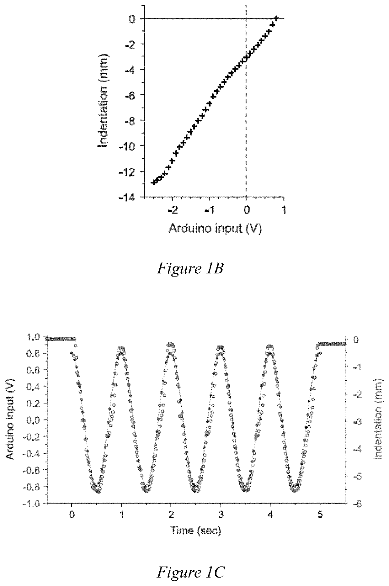
[0049]To operate the stretch device, a simple control circuit was designed in which an Arduino microcontroller (DEV-13975; SparkFun Electronics, Niwot, Colo.) modulated the magnitude and direction of a constant 6 A current from a DC power source (9129B; BK Precision, Yorba Linda, Calif.) to the coil via an H-bridge (RB-Cyt-132; RobotShop, Mirabel, Quebec, Canada). Two signals from the Arduino to the H-bridge controlled the current flow: A power-wave-modulation pin sending low voltage from 0 to 5 V controlled the current intensity (FIG. 8), and a digital pin (either 0 or 1) controlled the direction of the current to allow lifting of the piston in the relaxed state or attracting the piston downwards to intendent the engaged membrane. Arduino inputs were controlled via MATLAB (v. 2018b; The MathWorks, Natick, Mass.) via a USB interface and the Arduino Support from MATLAB package, and a custom-written code was used to operate the device.

example 3

tch Device—Calibration

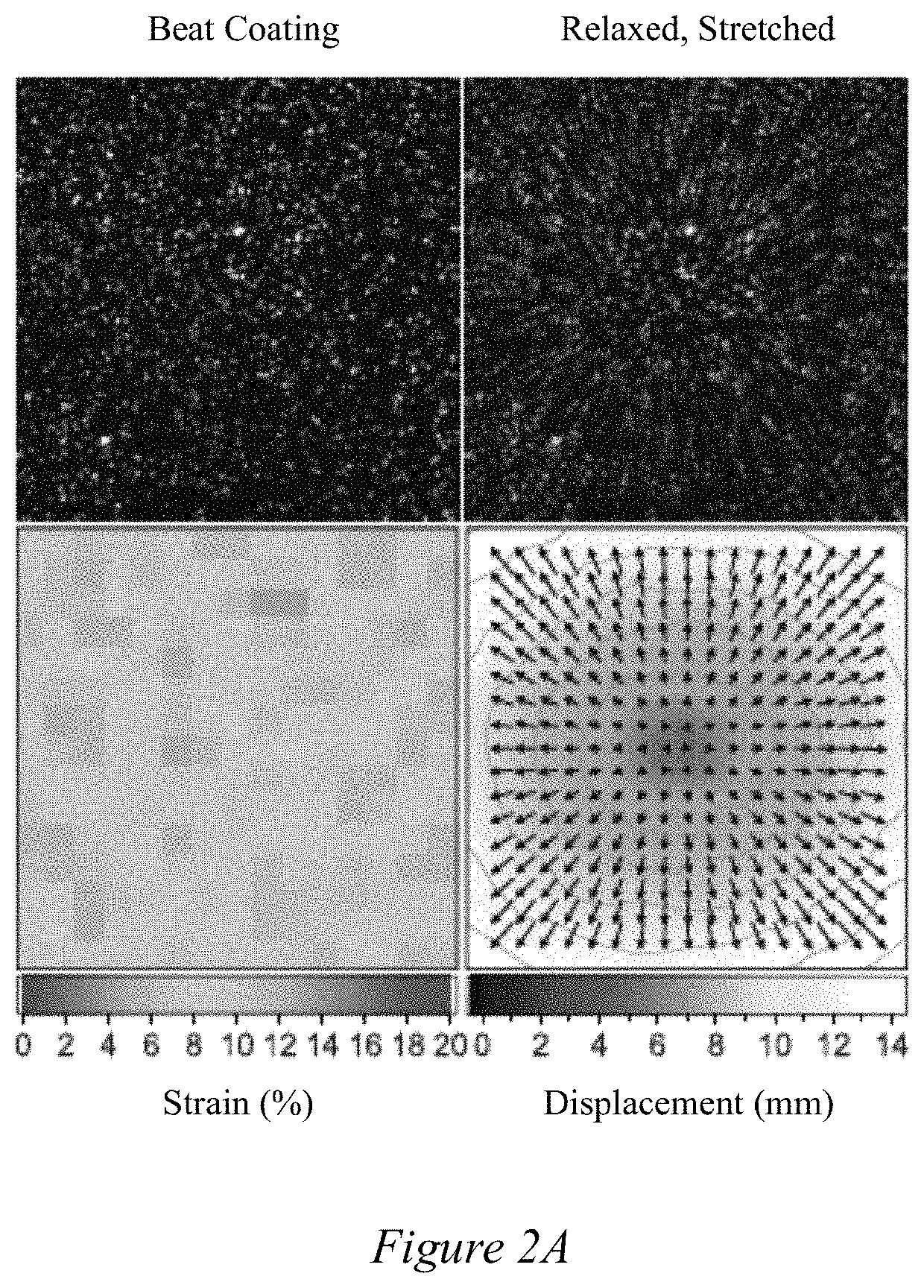
[0050]To measure piston movement and associated membrane indentation in response to electromagnetic fields, a laser distance sensor (LJ-G5001P; Keyence, Osaka, Japan) was pointed vertically at the top of the piston, and changes in vertical movement were recorded via the Keyence LJ-Navigator software (v. 1.7.0.0; Keyence). Particle tracking (L. Martiel, A. Leal, et al., M. ThéryMeasurement of cell traction forces with ImageJMethods Cell Biol, 125 (2015), pp. 269-287) was used to determine the amount of strain applied to the membrane in response to electromagnetic fields. For strain measurements, containment wells were coated with 2 μm blue fluorescent beads (F8824; Life Technologies, Carlsbad, Calif.), and images were recorded before and after membrane indentation on an inverted epifluorescence microscope (Ti-Eclipse; Nikon) with a 60× water immersion objective (0.26 μm / pixel) and an EMCCD camera (iXonEM+; Andor Technology, South Windsor, Conn.). Bead displaceme...


PUM


Abstract

A low-cost, magnetically-driven device that enables visualization and quantification of dynamic changes in cell behavior during mechanical stretch. Using this device, it was observed that nuclei of mouse embryonic skin fibroblasts underwent rapid but divergent responses to strain magnitude, showing nuclear area increase and chromatin decompaction during 5% (low) strain, but nuclear area decrease and chromatin condensation during 20% (high) strain. Only responses to low strain were dependent on calcium, while actin inhibition abrogated any nuclear response and increased stretch-induced DNA damage. Stretch-activation revealed a shift in actin filaments away from (low strain) or towards (high strain) the nuclear periphery. The findings suggest that different pathways control strain level-dependent cell behavior and that mechanical confinement of nuclei through actin may be a protective mechanism during high strain loads.

Description

CROSS-REFERENCE TO RELATED APPLICATIONS[0001]This application claims the benefit of U.S. Provisional Application No. 62 / 876,535, filed Jul. 19, 2019.STATEMENT OF GOVERNMENT INTEREST[0002]This invention was made with government support under grant number CMMI 1349735, awarded by the National Science Foundation. The government has certain rights in the invention.FIELD OF INVENTION[0003]This invention relates to methods and devices for controlled cell stretch and imaging.BACKGROUND OF THE INVENTION[0004]Mechanical cues from the environment are known to have a profound impact on cell fate and cell behavior, a phenomena referred to as mechanosensation. Changes in mechanical properties due to trauma, chronic conditions, or genetic predispositions lead to cellular degeneration and result in a range of pathologies. Understanding the mechanisms involved in mechanosensation would allow researchers to direct cell differentiation and behavior to generate artificial tissues for drug testing or o...

Claims


Application Information

Patent Timeline
IPC IPC(8): G01N3/10G01N3/06
CPCG01N3/10G01N3/068G01N3/08G01N2203/0286G01N2203/0089
Inventor NEU, COREY P.SEELBINDER, BENJAMINSCOTT, ADRIENNE K.NELSON, ISABEL
Owner UNIV OF COLORADO THE REGENTS OF
Why Eureka
Try Eureka