Temperature insensitive filter

a filter and temperature-sensitive technology, applied in the field of wavelength-selective optical filters and optical systems, can solve the problems of incompatibility with cmos, incompatibility with higher waveguide losses and cmos, and approach still suffers from drift, etc., to achieve densely integrated devices and compact systems.

Active Publication Date: 2022-06-14
UNIV GENT +1
View PDF14 Cites 0 Cited by
  • Summary
  • Abstract
  • Description
  • Claims
  • Application Information

AI Technical Summary

Benefits of technology

[0009]It is an advantage of embodiments of the present invention that a wavelength filter is provided that is substantially temperature insensitive and which is purely passive and does not require active control. It is an advantage of embodiments of the present invention that at least the thermo-optic effect inducing changes in refractive index is compensated for.
[0048]The present invention furthermore relates to an integrated spectrometer system, the system comprising a plurality of integrated wavelength-selective filter devices as described above, a plurality of light guiding circuits, and a plurality of integrated detectors, whereby each of the plurality of wavelength-selective filter devices is configured to have a different reference wavelength thereby defining a set of reference wavelengths, and whereby each of the plurality of light guiding circuits is adapted to receive a fraction of an externally applied radiation signal and to transmit it to one of the plurality of wavelength-selective filter devices for obtaining therefrom radiation of a specific reference wavelength and for directing the obtained radiation to one of the plurality of detectors. It is an advantage of embodiments of the present invention that a compact, mass producible and low cost stable spectrometer can be obtained.

Problems solved by technology

Optical wavelength filters in integrated photonic platforms tend to drift with temperature and this results in incorrect wavelength readings.
However, these approaches typically suffer from chemical instability, higher waveguide losses and CMOS incompatibility.
However, this approach still suffers from a drift due to thermal expansion.
This approach is also sensitive to fabrication imperfections.
The main disadvantages of this approach are the large power dissipation and the complex control systems that are required.
Also, it is very difficult to reach sufficient stability for spectroscopic applications.
The gas cells nevertheless are expensive and the need for an external filter cancels the advantages of photonic integration.

Method used


Image

  • Temperature insensitive filter
  • Temperature insensitive filter
  • Temperature insensitive filter

Examples


Embodiment Construction

[0063]The present invention will be described with respect to particular embodiments and with reference to certain drawings but the invention is not limited thereto but only by the claims.

[0064]The terms first, second and the like in the description and in the claims, are used for distinguishing between similar elements and not necessarily for describing a sequence, either temporally, spatially, in ranking or in any other manner. It is to be understood that the terms so used are interchangeable under appropriate circumstances and that the embodiments of the invention described herein are capable of operation in other sequences than described or illustrated herein.

[0065]Moreover, directional terminology such as top, bottom, front, back, leading, trailing, under, over and the like in the description and the claims is used for descriptive purposes with reference to the orientation of the drawings being described, and not necessarily for describing relative positions. Because components...


PUM

PropertyMeasurementUnit
temperatureaaaaaaaaaa
angleaaaaaaaaaa
angle of incidenceaaaaaaaaaa

Abstract

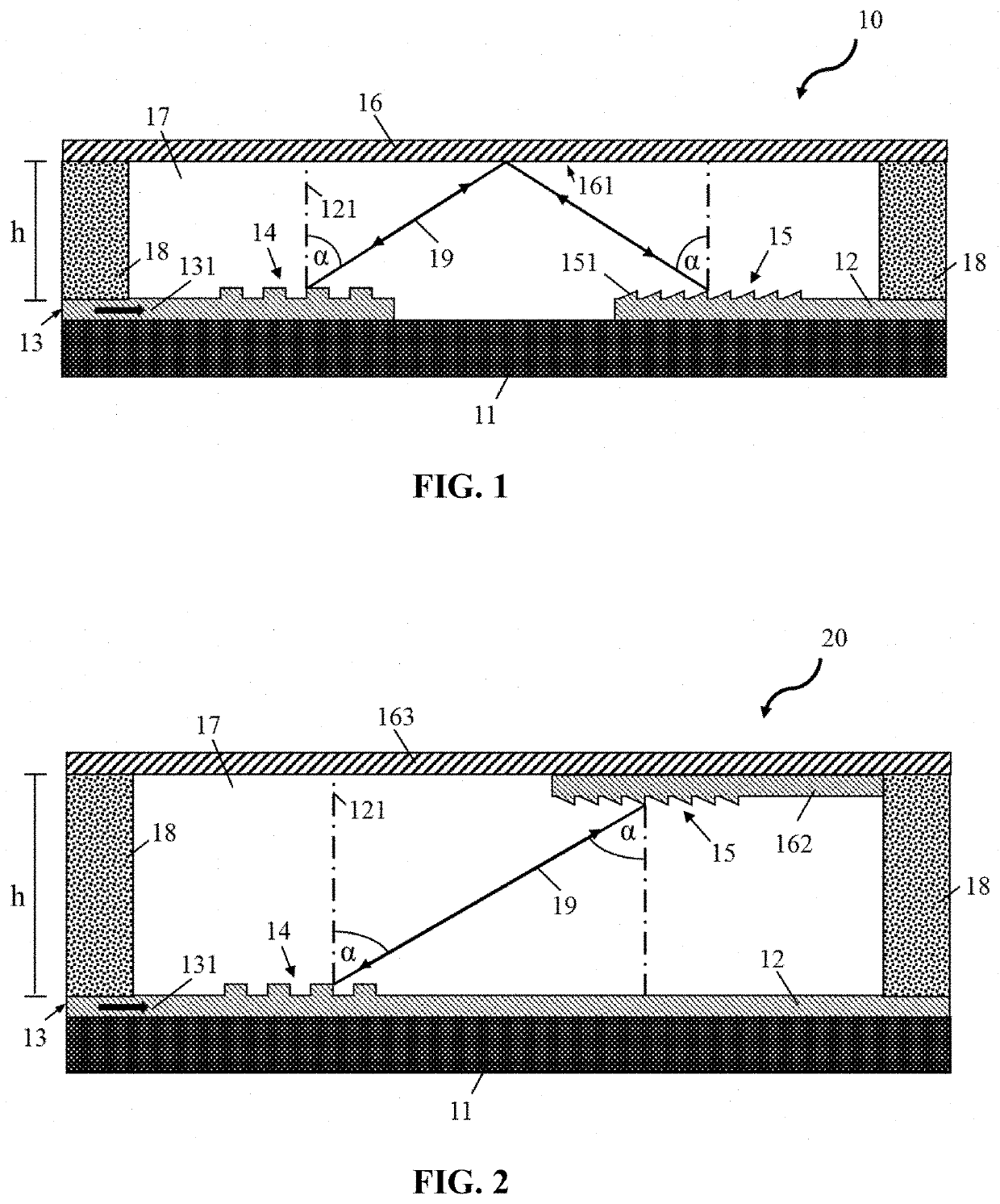
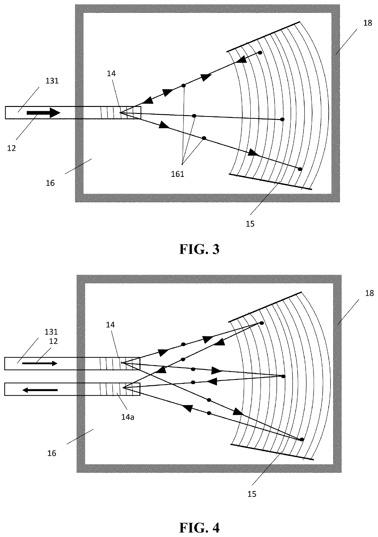
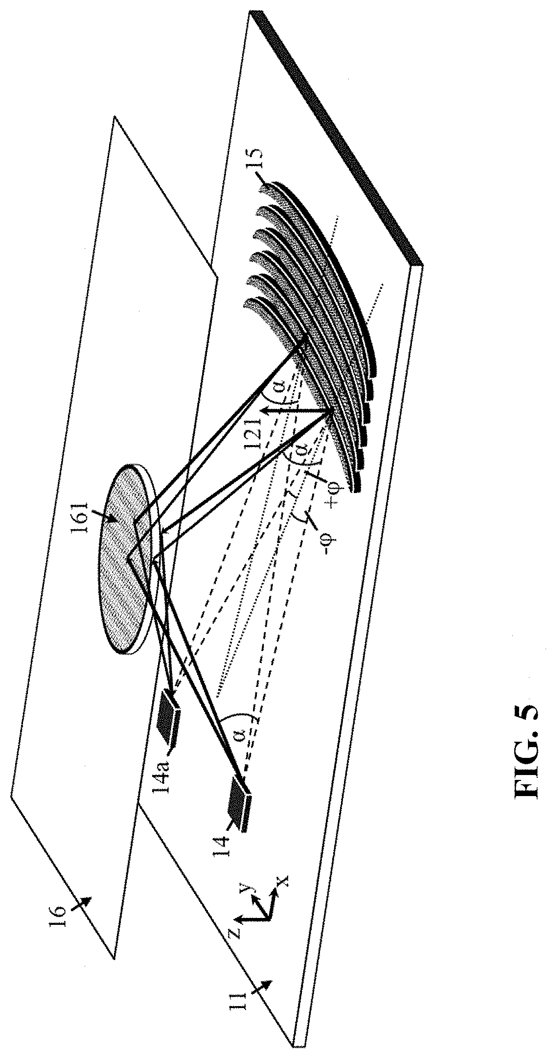
An integrated wavelength-selective filter device comprises a first optical element, for directing received radiation into a direction defined by a first angle, and a second optical element being a diffractive element configured for diffracting the directed radiation under a second angle. The second angle is such that for a single reference wavelength the diffracted radiation is directed into a propagation medium for advancing therein towards a predetermined position on the first optical element or on a further optical element for filtering radiation having a wavelength substantially matching the reference wavelength from radiation having a substantially different wavelength. The propagation medium is formed from a material that is different from any material of the substrate of the first and the second optical element.

Description

FIELD OF THE INVENTION[0001]The present invention generally relates to wavelength selective optical filters and optical systems including these filters, and more particularly, to integrated, athermal wavelength selective optical filters and integrated optical systems including these filters.BACKGROUND OF THE INVENTION[0002]Optical wavelength filters in integrated photonic platforms tend to drift with temperature and this results in incorrect wavelength readings. This is caused by two effects: the change of refractive index of the material due to the thermo-optic (TO) effect and thermal expansion of devices. Often the thermo-optic effect dominates, but for accurate measurements also the thermal expansion cannot be neglected. For spectroscopic applications or other applications where an absolute determination of optical wavelength is desired, active temperature tracking or the use of a fixed reference wavelength is required.[0003]In the past, a plurality of attempts have been made to ...

Claims


Application Information

Patent Timeline
Patent Type & Authority Patents(United States)
IPC IPC(8): G01J3/18G01J3/22G02B6/12G02B6/124G02B6/293G01J3/36G01J3/12
CPCG02B6/12007G02B6/124G02B6/29328G02B6/29398G01J3/1895G01J3/22G01J3/36G01J2003/1204G02B6/29326
Inventor BAETS, ROELANDRYCKEBOER, EVARAHIM, ABDULVASILIEV, ANTONNIE, XIAOMIN
Owner UNIV GENT
Why Eureka
Try Eureka