Capacitive device and piezoelectric device

a piezoelectric device and capacitive technology, applied in the direction of ultrasonic/sonic/infrasonic diagnostics, mechanical vibration separation, instruments, etc., can solve the problems of high-precision inspection, propagation efficiency of ultrasonic waves,

Active Publication Date: 2022-07-05
HITACHI LTD
View PDF13 Cites 0 Cited by
  • Summary
  • Abstract
  • Description
  • Claims
  • Application Information

AI Technical Summary

Benefits of technology

[0005]In non-destructive inspection using ultrasonic waves, in order to improve ultrasonic wave propagation efficiency, objects to be inspected are often immersed in water for the inspection.
[0011]According to the present invention, it is possible to achieve a capacitive device having improved sound propagation efficiency in the air.

Problems solved by technology

However, the states of many of the objects to be inspected changes due to swelling in water or water penetration, and thus, the objects to be inspected need to be inspected in the air.
However, the sound propagation efficiency of ultrasonic waves propagating in the air to a reception element is as low as 0.001%, which is an obstacle of high-precision inspection in the air.

Method used


Image

  • Capacitive device and piezoelectric device
  • Capacitive device and piezoelectric device
  • Capacitive device and piezoelectric device

Examples


first embodiment

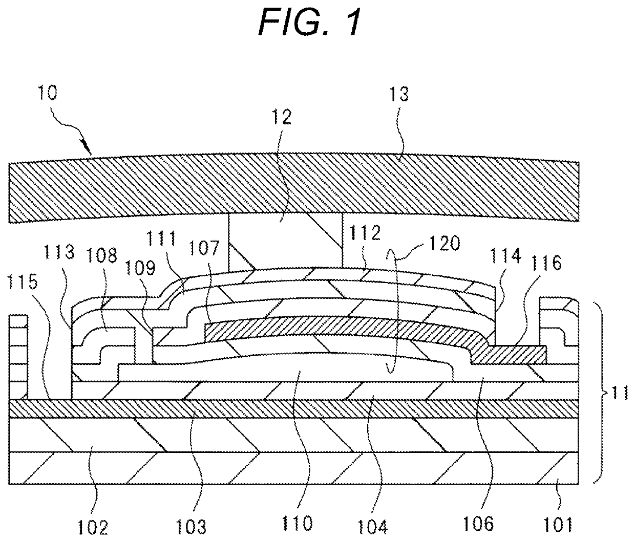
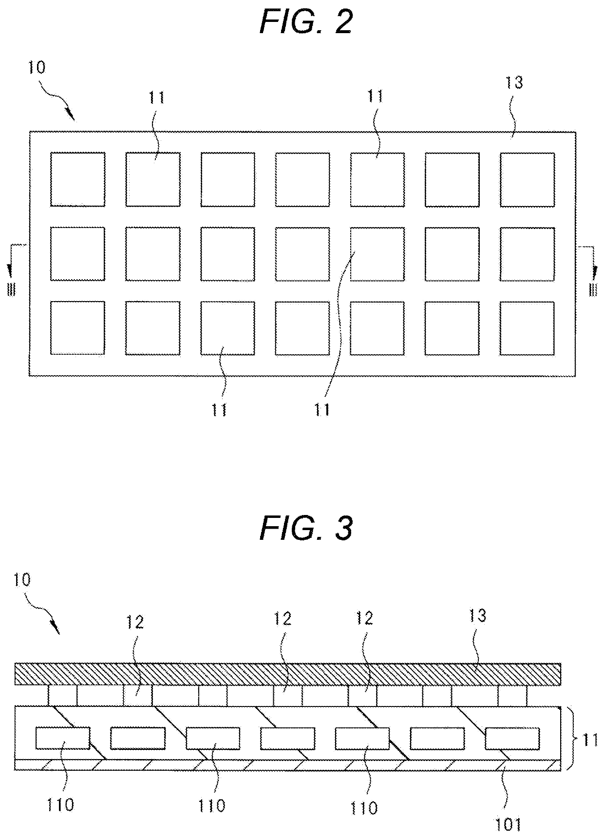
[0022]FIG. 1 is a cross-sectional view of a unit structure of a capacitive device 10 according to a first embodiment. The capacitive device 10 includes a unit cell 11 including a CMUT (ultrasonic transducer), and a transmission / reception plate 13 for impedance matching which is provided above the unit cell 11 via a connection portion 12.

[0023]The unit cell (CMUT) 11 includes a lower electrode 103 formed on a substrate 101 including monocrystalline silicon via an insulating film 102, two layers of insulating films 104 and 106 formed above the lower electrode 103, a hollow portion 110 defined by a gap formed between the two layers of the insulating films 104 and 106, an upper electrode 107 formed above the hollow portion 110 via the insulating film 106, and three layers of insulating films 108, 111, and 112 formed above the upper electrode 107. The insulating films 104, 106, 108, 111, and 112 include a silicon dioxide film.

[0024]Here, the insulating films 106, 108, 111, and 112 and th...

second embodiment

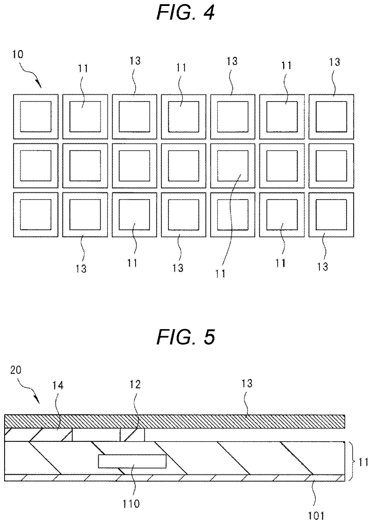
[0037]FIG. 5 is a schematic cross-sectional view of a unit structure of a capacitive device 20 according to a second embodiment. The capacitive device 20 according to the second embodiment is characterized in that one end of a transmission / reception plate 13 is supported by a unit cell 11 via a fixing portion 14 including an insulating film positioned in the same layer as a connection portion 12. Furthermore, a hollow portion 110 and a membrane 120 (see FIG. 1) above the hollow portion 110, both of which function as a CMUT, and the connection portion 12 are arranged at a position closer to the fixing portion 14 than the center portion of the transmission / reception plate 13. In other words, the hollow portion 110, the membrane 120, and the connection portion 12 are arranged at a position on a side closer to the fixing portion 14 (left side in FIG. 5) which is less likely to be deformed compared with the other end (right end in FIG. 5) of the transmission / reception plate 13.

[0038]The ...


PUM

PropertyMeasurementUnit
areaaaaaaaaaaa
impedanceaaaaaaaaaa
frequencyaaaaaaaaaa

Abstract

A capacitive device includes a unit cell including a CMUT, and a transmission / reception plate for impedance matching which is provided above the unit cell via a connection portion, in which a membrane of the CMUT constituting the unit cell is connected to the transmission / reception plate via the connection portion having an area smaller than that of the transmission / reception plate. The area of the transmission / reception plate is desirably larger than the area of a hollow portion of the CMUT.

Description

BACKGROUND OF THE INVENTION1. Field of the Invention[0001]The present invention relates to a capacitive device and a piezoelectric device, and more particularly to a capacitive device and a piezoelectric device which include a transmission / reception plate for impedance matching.2. Description of the Related Art[0002]An ultrasonic transducer element is incorporated in an ultrasonic probe (probe) of an ultrasonic imaging apparatus, transmitting and receiving ultrasonic waves and used for various purposes, such as diagnosis of a tumor in a human body or non-destructive inspection for cracks generated in a building.[0003]Conventionally, for this type of probes of ultrasonic imaging apparatuses, piezoelectric ceramics represented by lead zirconate titanate (PZT) or the like has been used as an electro-acoustic transducer element, but in recent years, capacitive micromachined ultrasonic transducers (hereinafter abbreviated as CMUTs) having wider bandwidth characteristics than that of the ...

Claims


Application Information

Patent Timeline
Patent Type & Authority Patents(United States)
IPC IPC(8): B06B1/02G01N29/24A61B8/00B06B1/06
CPCB06B1/0292A61B8/4494B06B1/067G01N29/245G01N29/2406A61B8/4483G01N29/06
Inventor TAKEZAKI, TAIICHIHASEGAWA, HIROAKIMACHIDA, SHUNTARO
Owner HITACHI LTD
Why Eureka
Try Eureka