
Controller for a cooling unit compressor, system and use

a technology for controlling a cooling unit and a compressor, which is applied in the direction of electric generator control, dynamo-electric converter control, dynamo-electric gear control, etc., can solve the problems of high electrical energy consumption of this technology in the range of 15 kw to 20 kw per day, lack of efficiency in terms of energy consumption of a system of this kind, and the inability to switch the motor on and o

Active Publication Date: 2022-08-02
EPPENDORF SE
View PDF11 Cites 0 Cited by
  • Summary
  • Abstract
  • Description
  • Claims
  • Application Information

AI Technical Summary

Benefits of technology

The present invention is a controller for a cooling unit compressor with at least one two-phase AC asynchronous motor. The technical effect of the invention is that it simplifies the hardware of the controller by not requiring complex control electronics for speed variation of the motor. The invention also ensures energy efficiency by reducing the electrical power consumption, particularly during a stationary cooling mode after down-cooling. The invention takes advantage of the fact that a system composed of first and second voltage converter means allows for flexible adaptation to different input voltages and allows for the use of a higher AC voltage in a maximum-power down-cooling mode. The voltage converter means ensure that the motor operates at a reduced power level in response to a temperature detection above a threshold. This reduces energy consumption and keeps the target temperature constant. The invention allows for simple control of the motor as a two-terminal device without requiring complex speed control or sensor signals. This is achieved by means of the voltage detector means at the mains inlet.

Problems solved by technology

Accordingly, the electrical energy consumption of this technology in the range of about 15 kW to 20 kW per day is high.
U.S. Pat. No. 8,011,191 B2 already addresses disadvantages of said state of the art and criticizes a lack of efficiency in terms of energy consumption of a system of this kind; for instance, the cooling circuits and thus the respective operating lines of the motors are configured for maximum load, which, while advantageous during down-cooling, will no longer be needed during the stationary cooling mode at the target temperature.
The cited state of the art criticizes in particular the fact that switching the motors on and off raises mechanical issues in addition to the disadvantages in efficiency and promotes vibration and noise generation.
While this solution seems elegant in principle and allows variability of the compressor motor output(s), this known approach is still not without disadvantages: for instance, the complexity of control and of the motor structure is significantly increased, wherein it has to be taken into account that the electrical rated outputs are in the kilowatt range, meaning that a significantly higher complexity in terms of controlling in connection with a corresponding motor design is required.
Moreover, in the sensitive technical field of ultra-low temperature cooling units, each additional required compressor feed line, such as a through-line of a cable for a speed sensor or the like, leads to issues regarding sealing and heat bridges and thus is disadvantageous on principle.
In the state of the art according to U.S. Pat. No. 8,011,191 B2, there is the additional problem that there, too, adaptation of the motor control to different mains voltage systems or predefined mains voltages of a particular supply network is possible only with significantly increased complexity of circuitry.
Finally, the respective mains voltage environments from (commonly public) supply networks offer another challenge, which affects the dimensions and the design of cooling unit compressors including their associated control: commonly, according to a particular network specification of a territory or country, a maximum current that can be drawn from said AC voltage supply network must not be exceeded.
While consumption points for higher currents may of course be established for special applications, they cause disproportionate costs on top of the additional work.

Method used


Image

  • Controller for a cooling unit compressor, system and use

Examples


Embodiment Construction

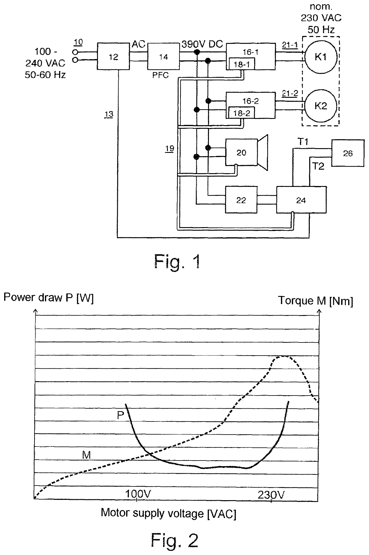
[0023]The schematic block diagram of FIG. 1 shows the substantial functional components for realizing the controller as per the invention according to the first preferred embodiment. Two AC asynchronous motors K1, K2, each configured for an AC voltage of 230 V at 50 Hz, can be controlled. In a manner otherwise known, such as from U.S. Pat. No. 8,011,191 B2, the cooling circuits each assigned to motors K1, K2 are connected to each other and cascaded in such a manner that a first cooling circuit, which is assigned to compressor motor K1, interacts with the surroundings of the device, which is embedded in a common housing or cabinet of an ultra-low temperature (ULT) cooling unit (not shown), while a second cooling circuit, which is coupled to said first cooling circuit by means of a heat exchanger (not shown), cools a cooling temperature which has been generated at the heat exchanger by the first cooling circuit further down to a target or useful cooling temperature of a cooling space ...


PUM


Abstract

The invention relates to a control apparatus for a refrigerator compressor having at least one two-phase AC asynchronous motor (K1, K2), having mains connection means (10) for connection to a preferably public voltage supply network which nominally provides a mains AC voltage of between 85 V and 264 V, in particular between 100 V and 230 V, first voltage converter means (14) which are connected downstream of the mains connection means and are intended to generate an intermediate voltage, in particular an intermediate DC voltage, from the mains AC voltage, second voltage converter means (16-1, 16-2) which are connected downstream of the first voltage converter means and are intended to generate an output signal which is independent of a level and a mains frequency of the mains AC voltage, in particular has a constant voltage and / or frequency in periods, and is intended to control the refrigerator compressor with an AC voltage of a plurality of differently predefinable voltage levels, wherein the mains connection means are assigned voltage detector means (12) for capturing the mains AC voltage, the detector output signal from which can be evaluated by the second voltage converter means or control means (24) assigned to the latter for the purpose of generating a mains-voltage-dependent maximum value for a current of the output signal.

Description

BACKGROUND OF THE INVENTION[0001]The present invention relates to a controller for a cooling unit compressor having at least one two-phase AC asynchronous motor. Furthermore, the present invention relates to a system comprising such a controller in connection with a cooling unit compressor having two AC asynchronous motors, and the present invention relates to a use of both such a controller and such a system to realize a cooling unit in deep cooling temperature ranges.[0002]Generic controllers and cooling unit compressors of cooling units controlled by them relate in particular to the field of what is known as ultra-low temperature (Ult) freezers, cooling units of this kind, which are commonly used for industrial and research purposes, are capable of keeping a used cooling space at a cooling temperature below −40° C., typically even below −60° C. to up to −80° C. and below. A typical intended use of these devices is long-term cooling; that is, biological or medical samples or ingre...

Claims


Application Information

Patent Timeline
Patent Type & Authority Patents(United States)
IPC IPC(8): H02P21/14H02P3/24H02M7/04F25B49/02F25B7/00H02P27/04H02P1/42H02P1/44H02M5/458H02M5/44
CPCF25B49/022F25B7/00F25B49/025H02M5/44H02M5/458H02P1/426H02P1/44H02P27/047F25B2700/2104
Inventor UHLENDORF, RÜDIGERPOOLE, GARYMASON, GEORGEKAO, TED
Owner EPPENDORF SE
Learn More