Cool air/warm air generation system

A warm air and cold air technology, which is applied in the direction of mechanical power generation mechanism, refrigerator, refrigeration and liquefaction, etc., can solve the problems of complex mechanism, easy to enlarge the device, and great adverse effect of global warming, etc., to achieve energy efficiency, The effect of high energy efficiency

Active Publication Date: 2019-09-13
NGK INSULATORS LTD
View PDF15 Cites 0 Cited by
  • Summary
  • Abstract
  • Description
  • Claims
  • Application Information

AI Technical Summary

Problems solved by technology

However, generally, the mechanism for compressing and expanding the working fluid is complicated, so there is a problem that the entire heat pump device tends to be enlarged.
In addition, among the above-mentioned heat pumps, the preferred working fluid from the viewpoint of improving energy efficiency is mostly a gas with a high global warming coefficient, which has a large adverse effect on global warming, and the use of this gas is against the demand of society as a whole to reduce greenhouse gases.
Therefore, there is also a problem that it is difficult to select the working fluid in a manner that meets the demand for reducing greenhouse gases and improves energy efficiency.

Method used


Image

  • Cool air/warm air generation system
  • Cool air/warm air generation system
  • Cool air/warm air generation system

Examples


Embodiment 1

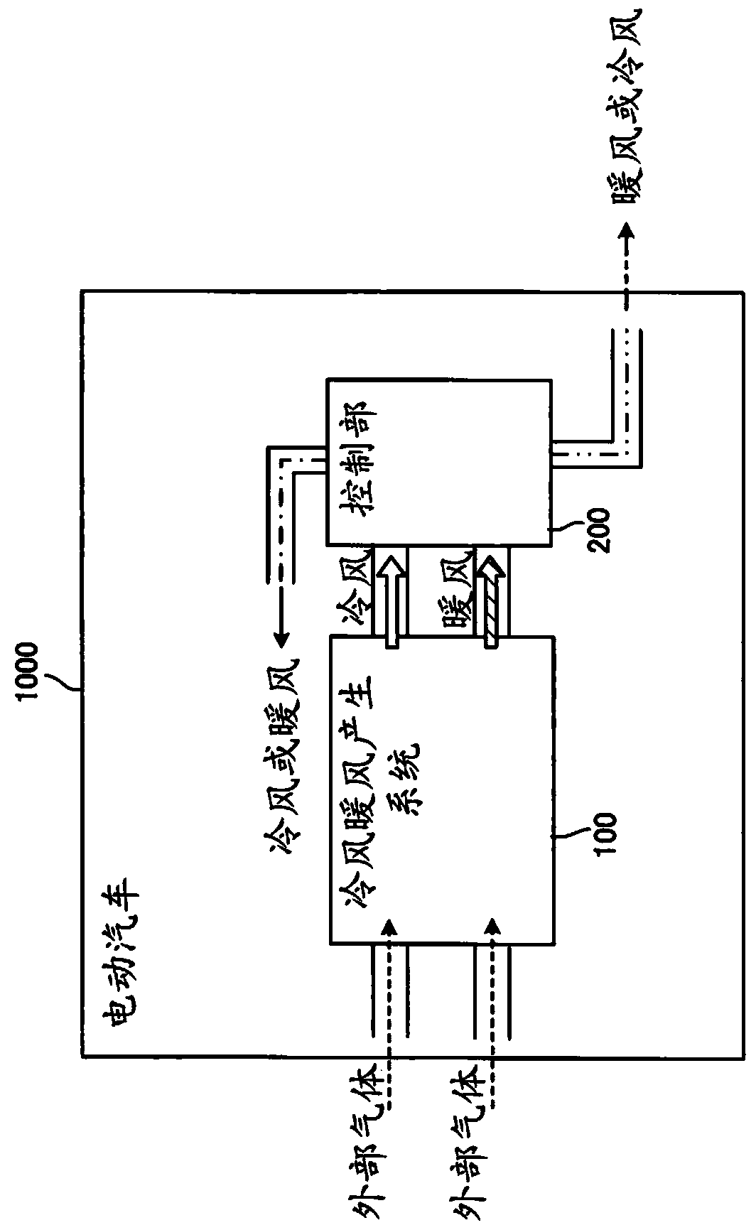
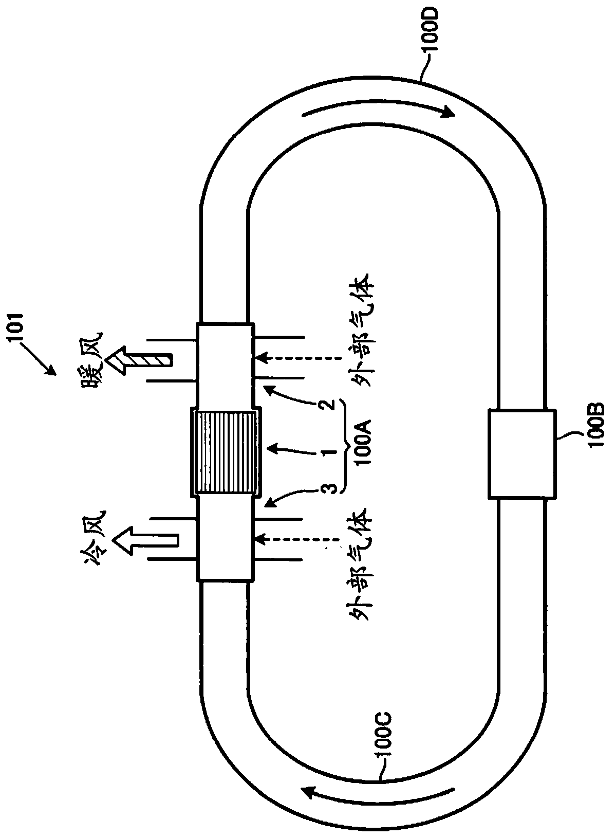
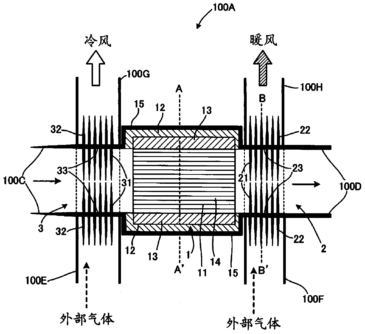
[0210] Example 1 uses the image 3 and Figure 4 100A of cold and warm wind generators and Figure 10 The sound wave generating part 100B of the figure 2 A specific example of the cold and warm wind generation system 101.

[0211] First, the cold air warm air generator in the first embodiment will be described. First, the thermoacoustic wave converting part of the cold air and warm air generating unit will be described.

[0212] As the thermoacoustic wave conversion member of the cold and warm air generation unit in Example 1, a honeycomb structure was used in which both the partition wall and the outer peripheral wall were made of a cordierite material with a thermal conductivity of 1.0 W / mK, and each cell was extended. In the cross-section of the entire thermoacoustic wave conversion member perpendicular to the direction of , the cell density of the area (cell structure area) occupied by the cross-section of the partition wall and the cross-section of the cell is 775 ce...

Embodiment 2~3 and comparative example 1~2

[0240] Except that the die used in the extrusion molding of the thermoacoustic wave conversion part is different, the same method as in the above-mentioned Example 1 is used to produce the thermoacoustic wave conversion part. The value of the cell density in the cell structure region is different from that of Example 1. The cold wind and warm wind generating systems of Examples 2-3 and Comparative Examples 1-2. Then, by the same method as in Example 1, energy efficiency, the degree of compactness, and the amount of noise were obtained and evaluated.

[0241] The evaluation results of Examples 1 to 3 and Comparative Examples 1 to 2 are shown in Table 1 below together with the values ​​of the above-mentioned parameters that characterize these Examples and Comparative Examples.

[0242] [Table 1]

[0243]

[0244] In Table 1, comparing Examples 1-3 and Comparative Example 2 shows that the energy efficiency and compactness of Examples 1-3 are very high compared with Comparativ...

Embodiment 4~5 and comparative example 3

[0246] In the manufacturing method of the thermoacoustic wave conversion member, except that the ceramic raw material is different, the same method as that of the above-mentioned Example 1 is used to produce a thermoacoustic wave conversion member that is different from that of Example 1 only in the thermal conductivity of the constituent materials of the partition wall or the outer peripheral wall. The cold wind and warm wind generation systems of Examples 4-5 and Comparative Example 3. Specifically, in Examples 4 to 5 and Comparative Example 3, the thermal conductivity was different from that of Example 1 by changing the proportions of talc, kaolin, alumina, and boehmite in Example 1.

[0247] The evaluation results of Examples 1, 4 to 5, and Comparative Example 3 are shown in Table 2 below together with the values ​​of the above-mentioned parameters that characterize these Examples and Comparative Examples.

[0248] [Table 2]

[0249]

[0250] In Table 2, comparing Exam...


PUM


Abstract

Provided is a cool air / warm air generation system for cooling and heating electric vehicles such that noise is suppressed while miniaturization of the whole system and high energy efficiency are achieved. The present invention comprises: a sound wave generator 100B which generates sound waves having a frequency in the range of 50-500 Hz by oscillating working fluid having a pressure of 35 atm or less by means of a linear motor; a first propagation tube 100C which allows the sound waves to propagate therethrough; and a cool air / warm air generator 100A which uses a heat-sound wave conversion component 1 having partition walls, which define a plurality of cells extending between two end faces, to cause a cool-air heat exchanger 3 to convert first outside air into cool air having a lower temperature and a warm-air heat exchanger 2 to convert second outside air into warm air having a higher temperature. In the cross-section of the heat-sound wave conversion component 1 perpendicular to thecell direction, the cell density in the cell structure region is within the range of 620-3100 cell / cm<2> and the thermal conductivity of the constituent material of the partition walls is 5.0 W / mK orless.

Description

technical field [0001] The invention relates to a cold and warm air generation system for cooling and heating the interior of an electric vehicle. Background technique [0002] In recent years, society as a whole has increasingly demanded the reduction of greenhouse gases such as carbon dioxide. In response to this demand, technological development of electric vehicles that do not use fossil fuels as a power source for engines has been actively developed in the automotive field. [0003] Electric vehicles can suppress the production of greenhouse gases such as carbon dioxide because they do not involve the combustion of fossil fuels, but they cannot use the waste heat of the engine as a heat source. For example, unlike a car that burns fossil fuels, an electric car cannot use waste heat from the engine as a heat source for heating the interior of the car, and must obtain other heat sources for heating the interior of the car. To put it simply, it is conceivable to obtain he...

Claims


Application Information

Patent Timeline
Patent Type & Authority Applications(China)
IPC IPC(8): B60H1/00B60H1/32F25B9/00B60H1/22
CPCB60H1/32F03G7/00F25B9/145B60H1/00392B60H1/00899B60H2001/00961B60H1/00428B60H2001/3292
Inventor 宫入由纪夫三轮真一
Owner NGK INSULATORS LTD
Why Eureka
Try Eureka