
Negative electrode and lithium ion secondary battery

a secondary battery and negative electrode technology, applied in the direction of active material electrodes, cell components, electrical equipment, etc., can solve the problems of oxidation/reduction reaction likely to be non-uniform, deposition becomes more prominent in the region where the reaction proceeds excessively, and capacity deterioration

Active Publication Date: 2022-08-09
TDK CORPARATION
View PDF15 Cites 0 Cited by
  • Summary
  • Abstract
  • Description
  • Claims
  • Application Information

AI Technical Summary

Benefits of technology

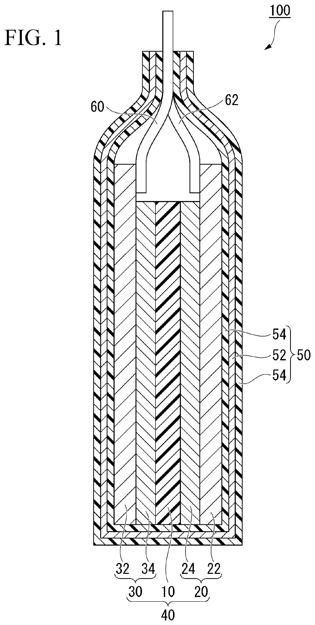
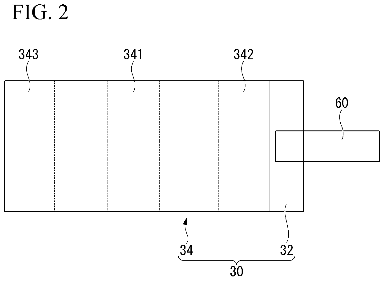
The present invention provides a negative electrode that reduces the deposition of precipitates and improves the cycle characteristics of a lithium ion secondary battery. The inventors discovered that a negative electrode layer with a larger phosphorus content in the central portion and a larger fluorine content in the end portion, as well as a larger water content in the central portion, exhibits improved cycle characteristics. Additionally, by suppressing wrinkle generation and non-uniformity in the oxidation / reduction reaction, the negative electrode reduces the metal lithium precipitation tolerance during repeated charge and discharge, resulting in a more stable and reliable lithium-ion battery.

Problems solved by technology

Therefore, the electrode body of the wound-type battery has a problem in that the oxidation / reduction reaction is likely to be non-uniform compared to that of the stacked-type battery.
Here, when the reaction in the electrode surface proceeds non-uniformly, such deposition becomes more prominent in the region where the reaction proceeds excessively.
In the region where the deposition has progressed, the conductivity decreases, and as a result, the internal resistance of the battery increases, the capacity deteriorates with repeated charge and discharge, and metal elution tends to occur.
However, in the method disclosed in the above documents, various characteristics have not yet been satisfied, and improvement of resistance to metal lithium deposition during repeated charge and discharge is required.

Method used


Image

  • Negative electrode and lithium ion secondary battery
  • Negative electrode and lithium ion secondary battery

Examples


example

Example 1

[0210]The negative electrode of Example 1 was produced by the following the steps A1 to A9.

[0211]Step A1

[0212]A negative electrode active material, a binder, and a solvent were mixed to prepare negative electrode mixture slurries A and B, respectively. The negative electrode mixture slurry A contains 98% by mass of a negative electrode active material, 1% by mass of a binder and 1% by mass of a solvent, and the negative electrode mixture slurry B contains 97% by mass of the negative electrode active material, 2% by mass of the binder and 1% by mass of the solvent. As the negative electrode active material in the negative electrode mixture slurries A and B, a natural graphite material for a lithium ion secondary battery was used. Further, a mixture of CMC as a thickener and SBR in a mass ratio of 1:1 was used as a binder. Water was used as a solvent. Separately, a 1% by mass solution of triphenyl phosphite as a phosphorus compound was added to the negative electrode mixture ...

example 2

[0243]A negative electrode was prepared in the same manner as in Example 1 except that in the step A2, a slurry prepared by mixing 40% by mass of the slurry A produced in the step A1 and 60% by mass of the slurry B produced in the step A1 was applied to the negative electrode current collector 32, so as to form a portion advanced by (⅙) L from the center between the first side and the second side toward the first side and the second side.

[0244]The ratio (P1 / P2) of the phosphorus content (P1) in the central portion 341 to the average phosphorus content (P2) in the first end portion 342 and the second end portion 343 was 1.16. The cycle characteristics after 1000 cycles were 85.5%.

[0245]The ratio (P1 / P3-1) of the phosphorus content (P1) to the phosphorus content (P3-1) at a first arbitrary point in the first end portion 342 and the second end portion 343 was 1.23. The ratio (P1 / P3-2) of the phosphorus content (P1) to the phosphorus content (P3-2) at a second arbitrary point in the fir...

example 3

[0246]A negative electrode was prepared in the same manner as in Example 1 except that in the step A2, a slurry prepared by mixing 33% by mass of the slurry A produced in the step A1 and 67% by mass of the slurry B produced in the step A1 was applied to the negative electrode current collector 32, so as to form a portion advanced by (⅙) L from the center between the first side and the second side toward the first side and the second side.

[0247]The ratio (P1 / P2) of the phosphorus content (P1) in the central portion 341 to the average phosphorus content (P2) in the first end portion 342 and the second end portion 343 was 1.24. The cycle characteristics after 1000 cycles were 85.1%.

[0248]The ratio (P1 / P3-1) of the phosphorus content (P1) to the phosphorus content (P3-1) at a first arbitrary point in the first end portion 342 and the second end portion 343 was 1.22. The ratio (P1 / P3-2) of the phosphorus content (P1) to the phosphorus content (P3-2) at a second arbitrary point in the fir...


PUM

PropertyMeasurementUnit
water contentaaaaaaaaaa

Abstract

A negative electrode includes a current collector and a negative electrode layer coated on at least one surface of the current collector. The negative electrode layer containing either phosphorus or fluorine, and the phosphorus content or fluorine content in the central portion of the negative electrode layer differs from the average phosphorus content in the end portion outward from the central portion to the side or the average fluorine content, and the phosphorus content P1 in the central portion and the average phosphorus content in the end portion P2 is 1<P1 / P2≤1.30, or the fluorine content F1 in the central portion and the average fluorine content F2 in the end portion of the negative electrode satisfy 1<F1 / F2≤1.22.

Description

TECHNICAL FIELD[0001]The present invention relates to a negative electrode and a lithium ion secondary battery.[0002]This application claims priority on Japanese Patent Application No. 2018-055176, Japanese Patent Application No. 2018-055253, and Japanese Patent Application No. 2018-055056 filed in Japan on Mar. 22, 2018, the contents of which are hereby incorporated by reference.BACKGROUND[0003]In recent years, electronic devices such as mobile phones and personal computers have rapidly become smaller and cordless, and there is an increasing demand for secondary batteries having a small size, light mass and high energy density as power sources for driving these devices. In particular, a lithium ion secondary battery having a large charge and discharge capacity and a high energy density has attracted attention. In the lithium ion secondary battery, capacity is obtained by intercalation and de-intercalation of Li+ solvated by oxidation / reduction reaction at the interface between the ...

Claims


Application Information

Patent Timeline
Patent Type & Authority Patents(United States)
IPC IPC(8): H01M4/62H01M10/05H01M10/0525H01M4/02
CPCH01M4/628H01M10/0525H01M2004/021H01M2004/027Y02E60/10
Inventor SHIMIZU, CHIEKO
Owner TDK CORPARATION
Learn More