
Decorative surface covering element, surface covering element covering, and method of producing such a decorative surface covering element

a technology of decorative surface covering and element, which is applied in the direction of flooring, covering/lining, construction, etc., can solve the problems of increasing labor and overall cost of the project, wasting time, and wasting tim

Active Publication Date: 2022-08-23
NORTHANN BUILDING SOLUTIONS LLC
View PDF33 Cites 0 Cited by
  • Summary
  • Abstract
  • Description
  • Claims
  • Application Information

AI Technical Summary

Benefits of technology

The patent describes a method for creating a three-dimensional bevel and grout line structure on a decorative layer without cutting away material during production. The method allows for improved design freedom and more realistic haptonomic properties of the bevel and grout line. The bevel and grout line structures can be printed on top of the decorative layer, improving the appearance of the line. The covering structure is designed with a recessed peripheral portion, allowing for a more realistic visual appearance of the line. The method also includes steps for curing the base layer and pattern layer to provide flexibility and prevent uncontrolled distribution of cut-away material. The upper surface of the covering structure can be treated with a brush roller to remove any cut-away material. The technical effect of this patent is an improved method for creating bevel and grout lines on decorative layers without cutting away material.

Problems solved by technology

Forming this separation between tiles is often tedious and requires the use of spacers to ensure uniformity and alignment of the tiles.
In general, the process of installing tile and creating the grout line involves a significant amount of time, which adds to the labor and overall cost of the project.
While this slight separation may be observable and in some cases may appear as a small seam or even as a micro groove, these types of known tiles do not offer any structure to represent or closely resemble the look and feel of a real grout line.
However, this cut-away of material at the tile edge(s) is laborious and leads to dust waste which is undesired from an economic and health point of view.
Moreover, by exposing the core to the atmosphere, and hence to moisture and temperature variations and fouling, during daily use may easily affect the core and therefore the tile (covering) as such.

Method used


Image

  • Decorative surface covering element, surface covering element covering, and method of producing such a decorative surface covering element
  • Decorative surface covering element, surface covering element covering, and method of producing such a decorative surface covering element
  • Decorative surface covering element, surface covering element covering, and method of producing such a decorative surface covering element

Examples


Embodiment Construction

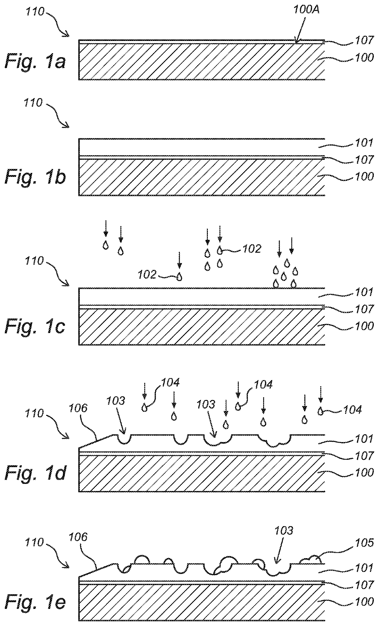
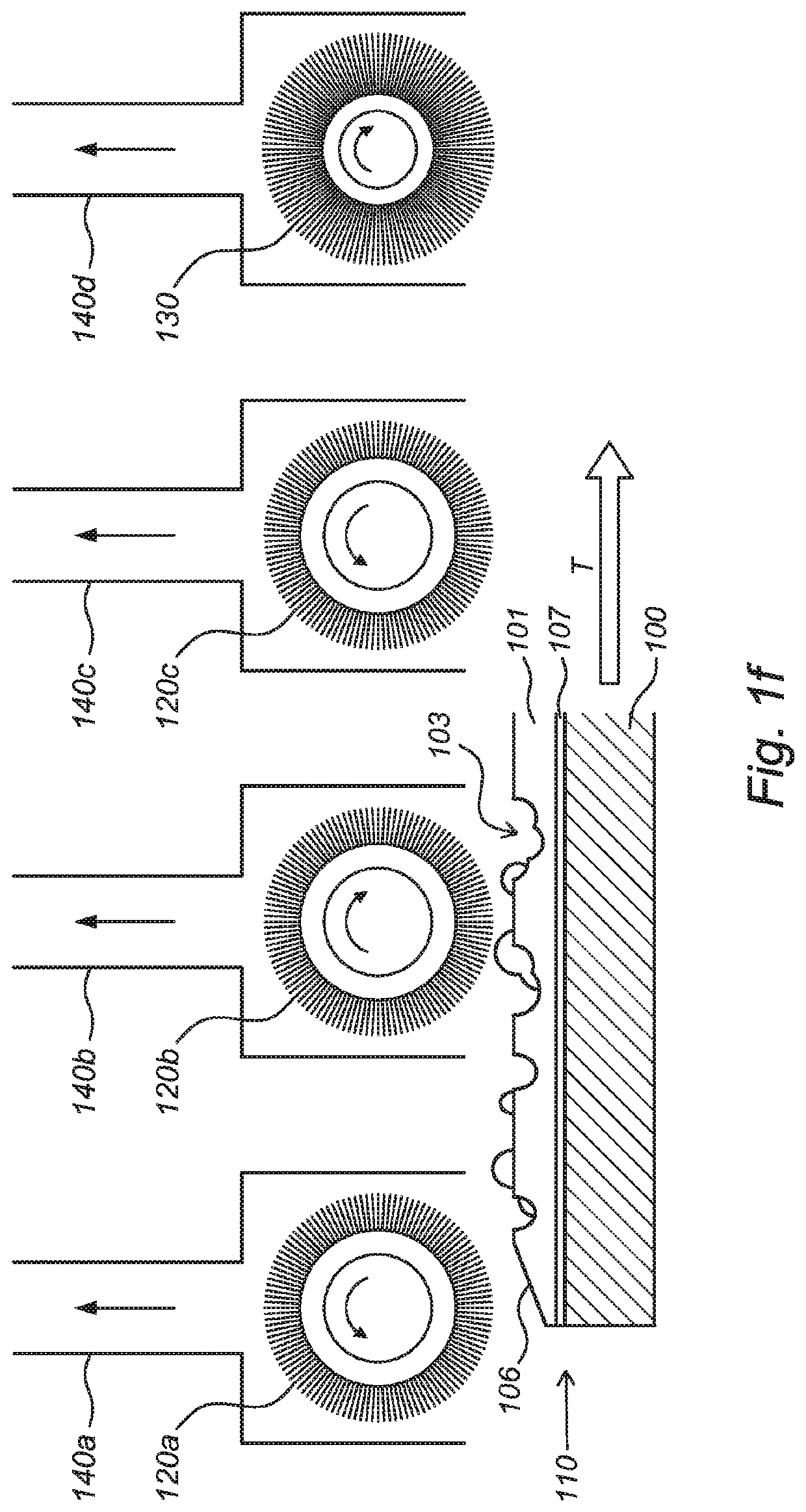
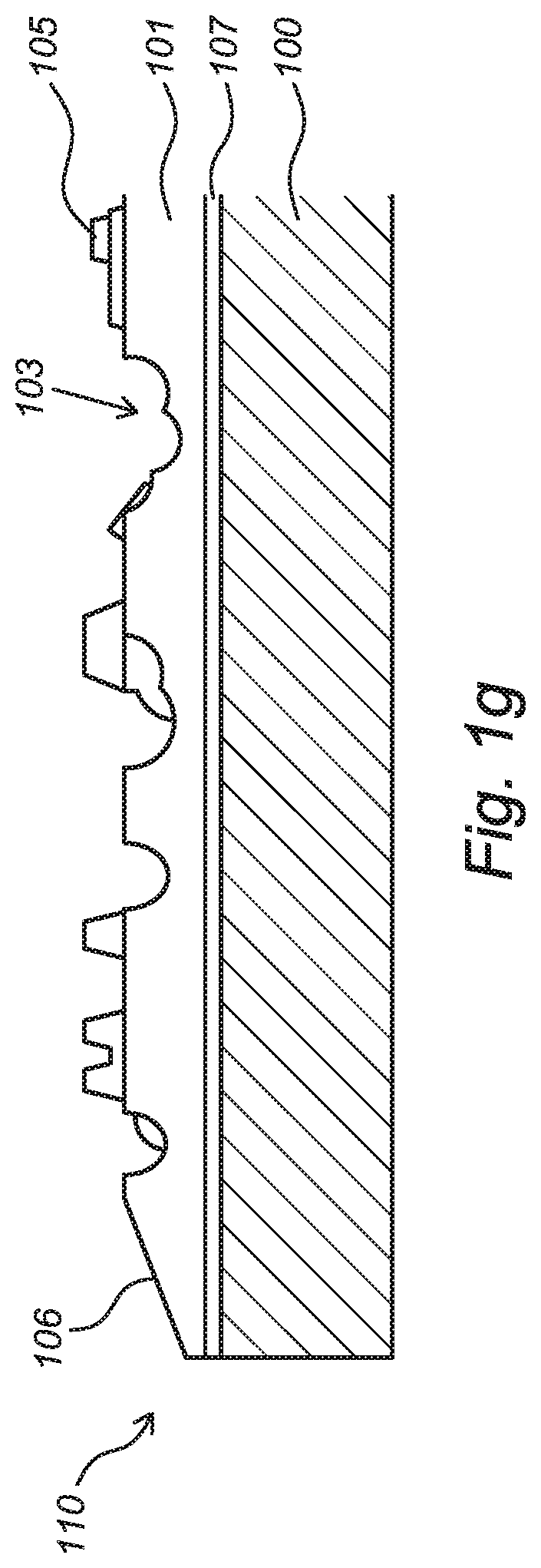
[0063]FIGS. 1a-1g show subsequent steps of a method according to the present invention. FIG. 1a shows a schematic representation of a cross section of a decorative panel (110) as an example of a surface covering element according to the invention. The figure shows the core (100) of the panel (110). The core (100) is typically substantially rigid, and may possibly comprises at least one polymer and / or at least one wood-based material. A decorative layer (107), in particular a décor image, is formed, preferably by means of digital printing, onto the upper side (100A) of the core (100) by means of printing, in particular digital printing. FIG. 1b show that a liquid base layer (101) is applied on the déor image formed at the upper side (100A) of the panel (110). The liquid forming the liquid base layer (101) is for example a UV sealer. The liquid base layer (101) generally has a relatively high surface tension in order to allow precise embossing in the liquid base layer (101). FIG. 1c s...


PUM

PropertyMeasurementUnit
heightaaaaaaaaaa
heightaaaaaaaaaa
angleaaaaaaaaaa

Abstract

The invention relates to a decorative surface covering element, in particular a floor panel, ceiling panel or wall panel. The invention also relates to a panel covering, such as a floor covering, ceiling covering or wall covering, comprising a plurality of panels according to the invention. The invention further relates to a method of producing a decorative surface covering element according to the invention.

Description

CROSS-REFERENCE TO RELATED APPLICATION[0001]This application claims priority to The Netherlands Patent Application No. 2025115 filed Mar. 12, 2020, the disclosure of which is hereby incorporated by reference in its entirety.BACKGROUND OF THE INVENTIONField of the Invention[0002]The invention relates to a decorative surface covering element, in particular a floor surface covering element, ceiling surface covering element or wall surface covering element. The invention also relates to a surface covering element covering, such as a floor covering, ceiling covering or wall covering, comprising a plurality of surface covering elements according to the invention. The invention further relates to a method of producing a decorative surface covering element according to the invention.Description of Related Art[0003]During the construction of a home, building or other structure, there will almost always be an unfinished floor surface such as a slab of concrete, a wood sub-structure or the lik...

Claims


Application Information

Patent Timeline
Patent Type & Authority Patents(United States)
IPC IPC(8): E04F13/08E04F15/02
CPCE04F13/0873E04F13/0866E04F13/0894E04F15/02038E04F2201/0138E04F2201/0153E04F2201/043E04F13/072E04F13/0876E04B9/04E04F15/02E04F13/0871E04F15/02033E04F15/02161E04F15/107E04F15/105E04F13/18B44C5/04B44C3/025
Inventor LI, LIN
Owner NORTHANN BUILDING SOLUTIONS LLC
Learn More