Supercharge Your Innovation With Domain-Expert AI Agents!

Method for manufacturing three-dimensional shaped object

a three-dimensional shaped object and manufacturing method technology, applied in the direction of additive manufacturing processes, manufacturing tools, and applying layer means, can solve problems such as problems, inability to suitably manufacture three-dimensional shaped objects having hollow portions in the interior thereof, and problems such as occurring

Active Publication Date: 2022-09-27
PANASONIC INTELLECTUAL PROPERTY MANAGEMENT CO LTD
View PDF15 Cites 0 Cited by
  • Summary
  • Abstract
  • Description
  • Claims
  • Application Information

AI Technical Summary

Benefits of technology

This approach allows for the suitable manufacturing of three-dimensional shaped objects with hollow portions, improving the ability to form complex structures and enhancing the structural strength and heat exchange efficiency when used as metal molds.

Problems solved by technology

Regarding the powder bed fusion and the LMD, the inventors of the present application have found that there may be occurred a problem with the latter, i.e., the LMD.
That is, the inventors have found that the problem may be occurred in a case where the three-dimensional shaped object having a hollow portion in the interior thereof is manufactured by the LMD.
With such physically difficult region for the formation of the new layer, the three-dimensional shaped object having the hollow portion in the interior thereof cannot be suitably manufactured.

Method used


Image

  • Method for manufacturing three-dimensional shaped object
  • Method for manufacturing three-dimensional shaped object
  • Method for manufacturing three-dimensional shaped object

Examples


Embodiment Construction

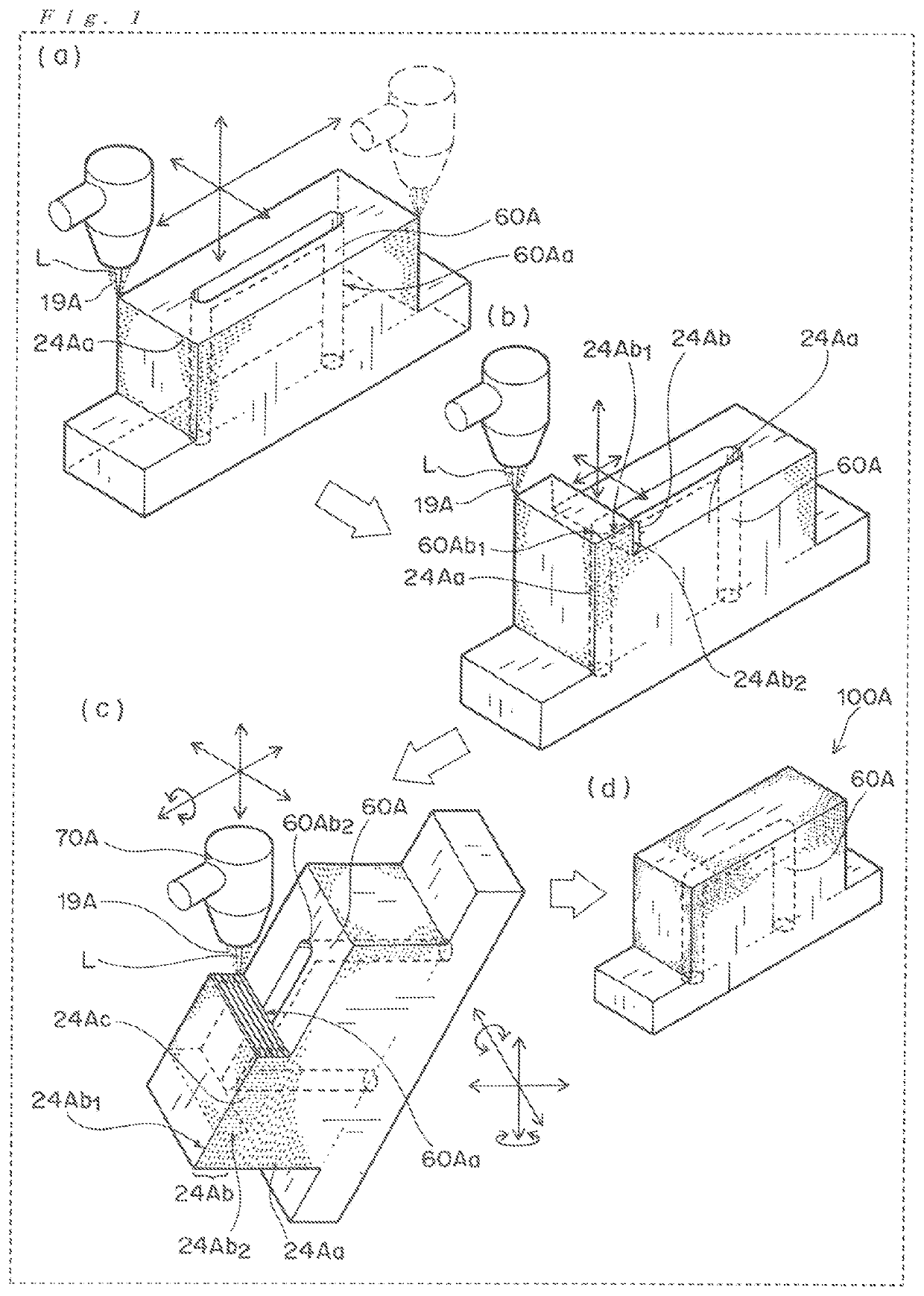
[0026]The manufacturing method according to an embodiment of the present invention will be described in more detail with reference to the accompanying drawings. It should be noted that configurations / forms and dimensional proportions in the drawings are merely for illustrative purposes, and thus not the same as those of the actual parts or elements.

[0027]The term “solidified layer” as used herein substantially means a “sintered layer” in a case where a metal powder for example is used as a raw material, and it substantially means a “cured layer” in a case where a resin powder for example is used as the raw material.

[0028]The directions of “upper” and “lower”, which are directly or indirectly used herein, are ones based on a stack direction of the solidified layers. The direction in which the solidified layers are stacked upon the manufacturing method of the present invention is “upper”, and the opposite direction thereto is “lower”. Conveniently, the lower direction can correspond t...


PUM

PropertyMeasurementUnit
heightaaaaaaaaaa
shapeaaaaaaaaaa
thicknessaaaaaaaaaa

Abstract

There is provided a method for manufacturing a three-dimensional shaped object by a continuous formation of a plurality of solidified layers through a light beam irradiation, the three-dimensional shaped object being provided with a hollow portion in an interior of the shaped object. The manufacturing method performs the formation of the solidified layer by irradiating a raw material with a light beam at the time of suppling the raw material, thereby allowing a sintering of the raw material or a melting and subsequent solidification of the raw material. In particular, a solidified foundation portion is provided as a part of the three-dimensional shaped object, the solidified foundation portion being used for a platform for a formation of a subsequent layer provided as the solidified layer. An orientation of the solidified foundation portion is changed prior to the formation of the subsequent solidified layer.

Description

TECHNICAL FIELD[0001]The disclosure relates to a method for manufacturing a three-dimensional shaped object. More particularly, the disclosure relates to a method for manufacturing a three-dimensional shaped object, in which a continuous formation of a plurality of solidified layers is performed through a light beam irradiation.BACKGROUND OF THE INVENTION[0002]Heretofore, a method for manufacturing a three-dimensional shaped object by a continuous formation of a plurality of solidified layers through a light beam irradiation has been known. For example, there is a “powder bed fusion” and a “LMD (Laser Metal Deposition)” as such method.[0003]The powder bed fusion can produce the three-dimensional shaped object by an alternate repetition of a powder-layer forming and a solidified-layer forming on the basis of the following (i) and (ii):[0004](i) forming a solidified layer by irradiating a predetermined portion of a powder layer with a light beam, thereby allowing a sintering of the pr...

Claims


Application Information

Patent Timeline
Patent Type & Authority Patents(United States)
IPC IPC(8): B29C64/153B22F3/105B22F3/16B33Y10/00B29C64/227B28B1/30
CPCB22F3/105B22F3/16B28B1/30B29C64/153B29C64/227B33Y10/00B29C64/232B29C64/236B29C64/241B29C64/209B22F5/10B22F5/007Y02P10/25B22F12/37B22F10/28B22F10/25B22F12/53
Inventor NAKAMURA, AKIFUMIYOSHIDA, NORIONAKASHIMA, NORIYASU
Owner PANASONIC INTELLECTUAL PROPERTY MANAGEMENT CO LTD
Features
  • R&D
  • Intellectual Property
  • Life Sciences
  • Materials
  • Tech Scout
  • Unparalleled Data Quality
  • Higher Quality Content
  • 60% Fewer Hallucinations
Learn More