Photoelectric conversion device for solar photovoltaic generation

a conversion device and photovoltaic technology, applied in the direction of semiconductor devices, basic electric elements, electrical equipment, etc., can solve the problems of increasing cost, energy loss, and large device siz

Active Publication Date: 2022-09-27
TOYOTA JIDOSHA KK
View PDF18 Cites 0 Cited by
  • Summary
  • Abstract
  • Description
  • Claims
  • Application Information

AI Technical Summary

Benefits of technology

[0005]The present disclosure provides a configuration of a photoelectric conversion device configured such that sunlight (or sunlight energy) is concentrated and a photoelectric cell is irradiated with the concentrated sunlight and solar photovoltaic generation is performed at the photoelectric cell, with which it is possible to improve sunlight energy use efficiency even when a high-precision sun-tracking mechanism is not used or to reduce energy loss occurring when power is obtained from sunlight as much as possible.
[0015]Depending on the type of the fluorescent substances in the fluorescent light guide plate of the above-described device of the present disclosure, significant re-absorption of fluorescent light may occur and thus energy loss may be made large. Therefore, the amount of fluorescent substances may be reduced for a region in the fluorescent light guide plate where the sunlight is not likely to reach like the vicinity of a portion where the first photoelectric cell is disposed so that re-absorption of fluorescent light is reduced. Therefore, in the device, the distribution of the fluorescent substances in the fluorescent light guide plate may be adjusted such that the density of the fluorescent substances in a region where light incident from the first surface does not reach is lower than the density of the fluorescent substances in a region where the light incident from the first surface reaches in the fluorescent light guide plate. Accordingly, the amount of re-absorption of the fluorescent light is reduced, the amount of unnecessary fluorescent substances is reduced, and the amount of use of the fluorescent substances can also be reduced.
[0016]Meanwhile, the device of the present disclosure is expected to improve photoelectric conversion efficiency robustness with respect to the angle of incidence of sunlight and thus is expected to be able to be applied onto objects having various shapes, such as a roof of a moving object. In this case, it is preferable that the device can be deformed to some extent in accordance with the shape of an object. Therefore, in the above-described device of the present disclosure, the fluorescent light guide plate and the lens layer may be formed of a flexible material.
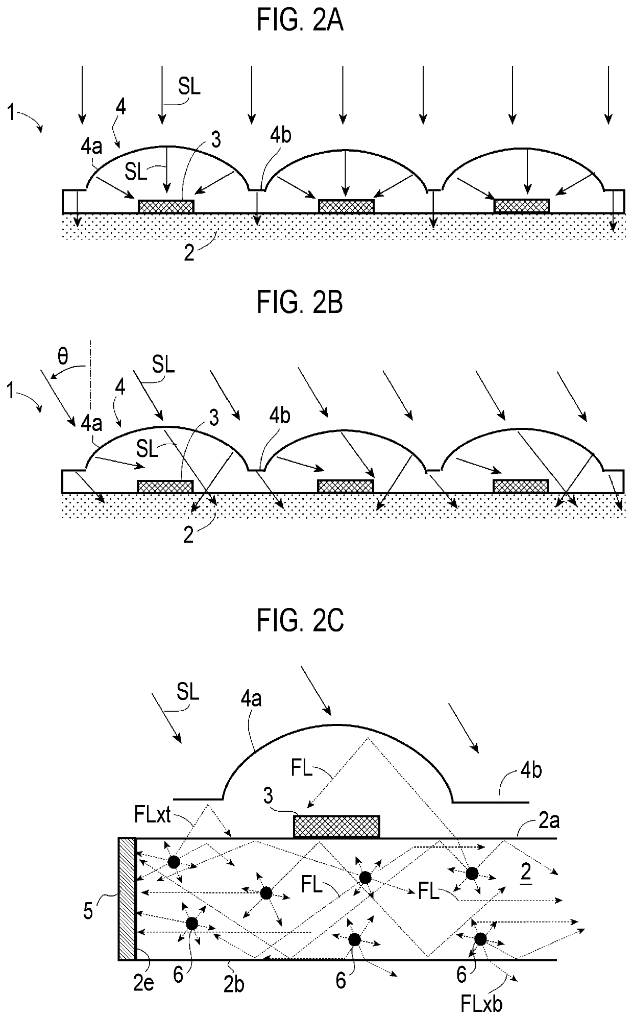
[0017]Accordingly, according to the present disclosure described above, in the photoelectric conversion device in which sunlight is concentrated, the photoelectric cells are irradiated with the concentrated sunlight, and solar photovoltaic generation is performed at the photoelectric cells, a majority of light concentrated by the lens layer is absorbed by the first photoelectric cell and light that does not reach the first photoelectric cell is absorbed by the second photoelectric cell via the fluorescent light guide plate so that power generation is performed by means of photoelectric conversion for each light. Therefore, it is possible to improve power generation efficiency robustness with respect to the angle of incidence of sunlight. Therefore, it is expected that both of efficiency maximization and maintenance of robustness can be achieved when the efficiency of the first photoelectric cell, which absorbs the sunlight as it is to generate power, is maximized. Furthermore, according to the present disclosure, robustness against a change in angle of incidence of the sunlight at the lens portion of the photoelectric conversion device is improved and thus a range of allowable angles of incidence of sunlight at the lens portion is widened. Therefore, it is expected that a power generation efficiency requirement can be achieved in many cases without a sun-tracking mechanism and it is possible to advantageously reduce a tracking precision to be satisfied even in a case where a sun-tracking mechanism is used.

Problems solved by technology

However, in a case where the sun-tracking mechanism that causes the orientations of the lens and the cell to follow the orientation of the sunlight at a high precision is provided, there is a probability that a configuration is made large, the size of the device is made large, and the cost increases.
However, since energy applied to the photoelectric cell is fluorescent light energy obtained when sunlight energy is converted by the fluorescent substances, energy loss may occur in a conversion step thereof depending on the quantum yield of the fluorescent substances or a difference between an absorption wavelength and a light emission wavelength of light.
However, the first photoelectric cell is not irradiated with components of the sunlight that miss the lens portion or components of the sunlight of which the angle of incidence with respect to the lens portion is large and it is difficult to irradiate, by means of the light concentration action of the lens layer, the first photoelectric cell with all of the sunlight with which the lens layer is irradiated.
Depending on the type of the fluorescent substances in the fluorescent light guide plate of the above-described device of the present disclosure, significant re-absorption of fluorescent light may occur and thus energy loss may be made large.

Method used


Image

  • Photoelectric conversion device for solar photovoltaic generation
  • Photoelectric conversion device for solar photovoltaic generation
  • Photoelectric conversion device for solar photovoltaic generation

Examples


Embodiment Construction

Basic Configuration of Photoelectric Conversion Device

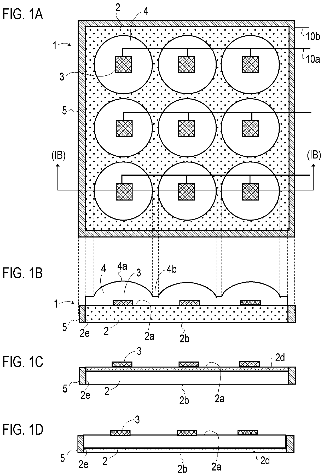
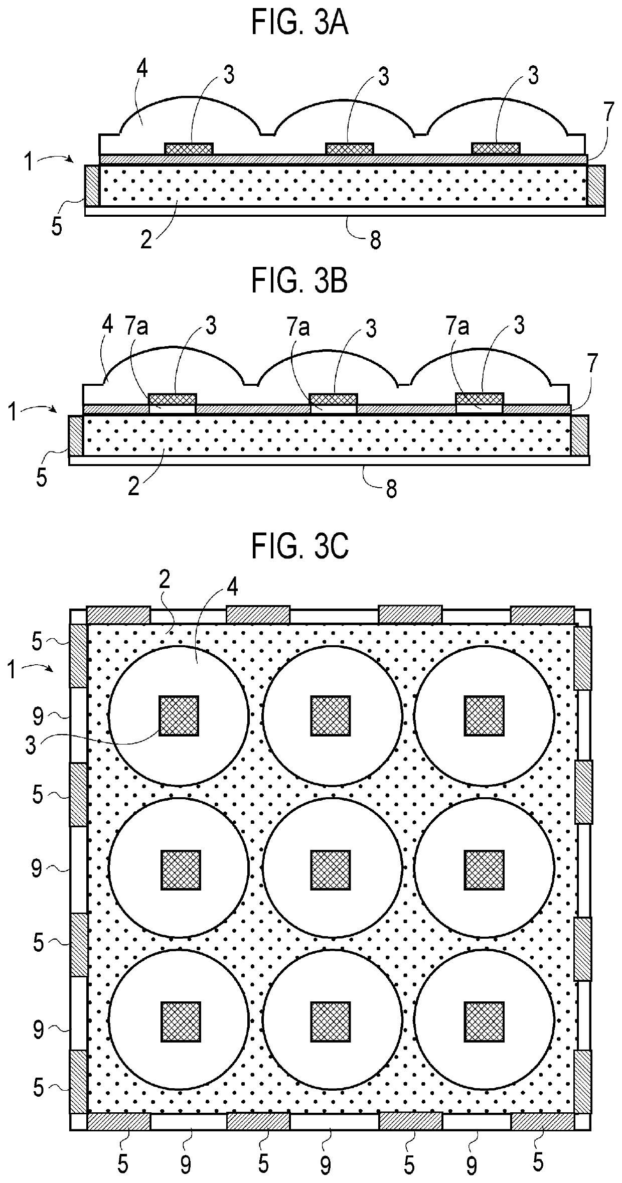
[0032]With reference to FIGS. 1A and 1B, the basic configuration of a photoelectric conversion device 1 of the present embodiment includes a fluorescent light guide plate 2 having a plate-shaped structure, photoelectric cells (first photoelectric cells) 3 mounted on a first surface (upper surface in drawings) 2a of the fluorescent light guide plate 2, a lens layer 4 overlapping the upper surface 2a of the fluorescent light guide plate 2 and the photoelectric cells 3, and a photoelectric cell (second photoelectric cell) 5 disposed on edge surfaces 2e of the fluorescent light guide plate 2. As shown in the drawings, power generated by the photoelectric cells 3 and 5 may be extracted through power lines 10a and 10b.

[0033]In the above-described photoelectric conversion device 1, as shown in the drawings, the fluorescent light guide plate 2 is used as a substrate on which the photoelectric cells 3 that absorb sunlight to generate pow...


PUM

PropertyMeasurementUnit
thicknessaaaaaaaaaa
angleaaaaaaaaaa
angleaaaaaaaaaa

Abstract

A photoelectric conversion device includes: a fluorescent light guide plate that has a plate-shaped structure in which fluorescent substances that absorb sunlight and emit fluorescent light are dispersed and which is formed of a material having a refractive index different from a refractive index of an outside, the fluorescent light emitted from the fluorescent substances being concentrated onto an edge surface to be emitted when the sunlight is incident; a first photoelectric cell configured to generate power by being irradiated with the sunlight; a lens layer configured such that light incident from an outer surface is concentrated onto the first photoelectric cell; a second photoelectric cell configured to generate power by being irradiated with the fluorescent light emitted from the edge surface of the fluorescent light guide plate; and power output units configured to extract power obtained in the photoelectric cells.

Description

CROSS-REFERENCE TO RELATED APPLICATION[0001]This application claims priority to Japanese Patent Application No. 2020-170813 filed on Oct. 8, 2020, incorporated herein by reference in its entirety.BACKGROUND1. Technical Field[0002]The present disclosure relates to a photoelectric conversion device in which a photoelectric cell is supported on a substrate, and more specifically, relates to a photoelectric conversion device configured to concentrate sunlight and irradiate a photoelectric cell with the concentrated sunlight.2. Description of Related Art[0003]In order to reduce a cost or dimensions of a solar photovoltaic generation system by increasing the amount of power generation per photoelectric cell (examples thereof include solar cell) in the system or decreasing the number of photoelectric cells to be used while improving the power generation efficiency in the system, various configurations of a solar cell module or a photoelectric conversion device for concentration of sunlight...

Claims


Application Information

Patent Timeline
Patent Type & Authority Patents(United States)
IPC IPC(8): H01L31/055H01L31/054H01L31/046
CPCH01L31/055H01L31/046H01L31/0543H01L31/0547H01L31/042Y02E10/52
Inventor OKUMURA, KENICHIMASUDA, TAIZOTOMIZAWA, RYOTA
Owner TOYOTA JIDOSHA KK
Why Eureka
Try Eureka