Microstrip mixer and microwave-doppler detecting module

Active Publication Date: 2022-10-04
ZOU GAODI
View PDF2 Cites 0 Cited by
  • Summary
  • Abstract
  • Description
  • Claims
  • Application Information

AI Technical Summary

Benefits of technology

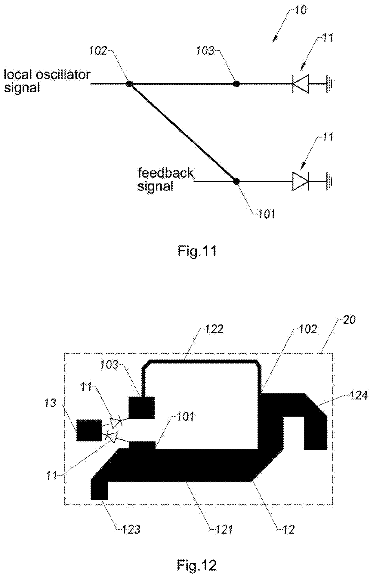
The present invention provides a microstrip mixer and microwave-doppler detecting module with improved flexibility and reduced size. The microstrip mixer has an open structure with three ports, making it more adaptable to different circuit structures. The flexible microstrip structure design also helps to reduce the size of the microstrip mixer, which in turn reduces the size of the circuit board and microwave-doppler detecting module that uses it.

Problems solved by technology

Conventional microwave-doppler detecting modules mostly utilize integral structure for receiving and dispatching due to the considerations in cost and size.
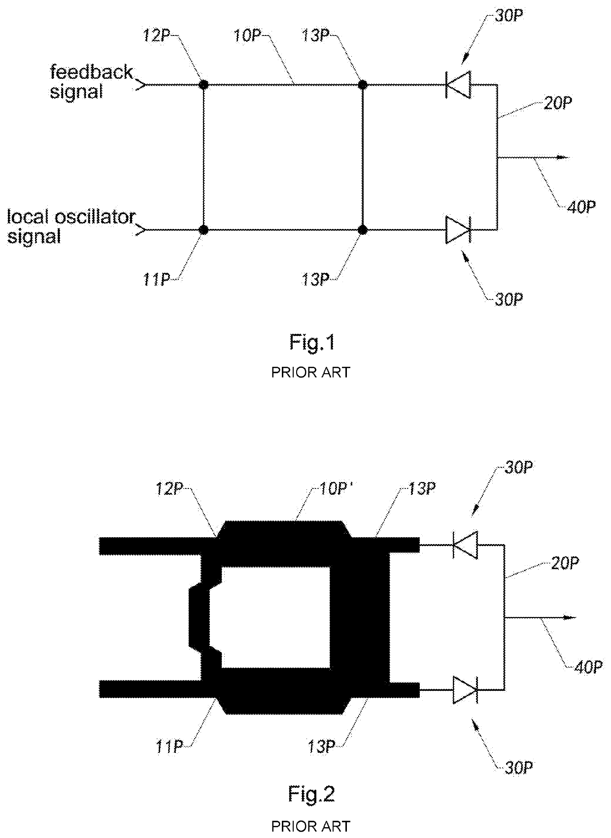
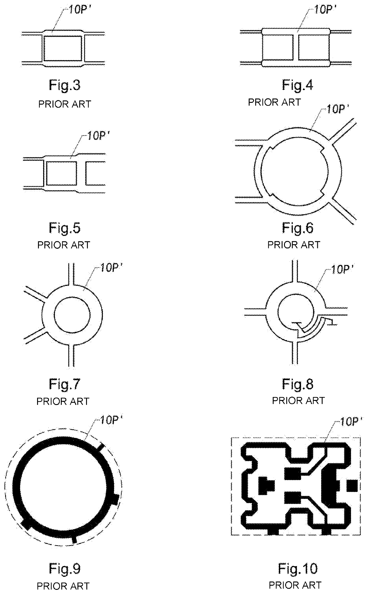
Besides, the corresponding positions of the local oscillator signal input port 11P, the feedback signal input port 12P, and the two mixing output ports 13P and 14P are restricted based on the structure of the microstrip frame 10P′, which not only makes it difficult to further reduce the occupied volume of the microstrip balanced mixer, but also limits the corresponding circuit of the circuit board having the microstrip balanced mixer disposed thereon.
That is, the size of the circuit board can hardly be reduced and the design of the corresponding circuit on the circuit board must consider the positions of the ports of the electric bridge 10P, that makes the designing harder.
The flexible implementations of the electric bridge 10P cannot provide any advantage for simplifying the design of the circuit of the microstrip balanced mixer.
As a result, the area size of the circuit board with a conventional microstrip balanced mixer can hardly be reduced for achieving miniaturization and modularization purposes and the difficulty of designing the circuit is high.
Accordingly, further reducing the size of the microwave-doppler detecting module that utilizes the microstrip balanced mixer costs higher in circuit designing.

Method used


Image

  • Microstrip mixer and microwave-doppler detecting module
  • Microstrip mixer and microwave-doppler detecting module
  • Microstrip mixer and microwave-doppler detecting module

Examples


Embodiment Construction

[0068]The following description is disclosed to enable any person skilled in the art to make and use the present invention. Preferred embodiments are provided in the following description only as examples and modifications will be apparent to those skilled in the art. The general principles defined in the following description would be applied to other embodiments, alternatives, modifications, equivalents, and applications without departing from the spirit and scope of the present invention.

[0069]Those skilled in the art should understand that, in the disclosure of the present invention, terminologies of “longitudinal,”“lateral,”“upper,”“front,”“back,”“left,”“right,”“perpendicular,”“horizontal,”“top,”“bottom,”“inner,”“outer,” and etc. just indicate relations of direction or position are based on the relations of direction or position shown in the appended drawings, which is only to facilitate descriptions of the present invention and to simplify the descriptions, rather than to indi...


PUM


Abstract

A microstrip mixer of a microwave-doppler detecting module has a shared port, a local oscillator signal input port and a mixing output port and includes two mixer tubes. The local oscillator signal input port is electrically connected with the shared port and is electrically connected with an end of one of the mixer tubes through the shared port. The local oscillator signal input port is also electrically connected with the mixing output port and is electrically connected with an end of the other mixer tube through the mixing output port. The other ends of the two mixer tubes are respectively grounded. Accordingly, the microstrip mixer is configured to have an open structure having three ports, which is more flexible and enhances the applicability thereof while reducing the size of the microwave-doppler detecting module utilizing the microstrip mixer.

Description

CROSS REFERENCE OF RELATED APPLICATION[0001]This is a non-provisional application that claims the benefit of priority under 35 U.S.C. § 119 to Chinese applications, application number 201911278690.6, filed Dec. 13, 2019.BACKGROUND OF THE PRESENT INVENTIONField of Invention[0002]The present invention relates to the field of microwave-doppler sounding and detecting, and more particularly to a microstrip mixer of a microwave-doppler detecting module with an integral structure for receiving and dispatching, and a microwave-doppler detecting module having the microstrip mixer.Description of Related Arts[0003]With development of IOT (Internet of things), artificial intelligence (AI), intelligent home, and intelligent security have higher and higher demands in the accuracy of the detection of the environment, especially for the existence, movements, and motion characteristics of fine motions of human. Here, microwave detection technology based on Doppler Effect is utilized as a critical ke...

Claims


Application Information

Patent Timeline
IPC IPC(8): G01S7/03G01S13/53G01S13/56G01S13/536H01P3/08H03D7/02
CPCG01S7/032G01S13/536G01S13/56H01P3/081H03D7/02H03D7/16G01S7/02H03D9/0633
Inventor ZOU, GAODIZOU, XIN
Owner ZOU GAODI
Why Eureka
Try Eureka