Supercharge Your Innovation With Domain-Expert AI Agents!

Piezoelectric actuator, vibration generating device and electronic equipment

a technology of vibration generating device and actuator, which is applied in the direction of device details, piezoelectric/electrostrictive device details, microphone structure association, etc., can solve the problems of difficult enhancement of the adhesiveness of the conductive joining member to the external electrode, and achieve the effect of suppressing the breakage enhancing the adhesiveness of the conductive joining member

Active Publication Date: 2022-10-11
TAIYO YUDEN KK
View PDF8 Cites 0 Cited by
  • Summary
  • Abstract
  • Description
  • Claims
  • Application Information

AI Technical Summary

Benefits of technology

The invention improves the adhesion between a conductive joining member and an external electrode while preventing breakage caused by the vibration of a piezoelectric element.

Problems solved by technology

However, in the piezoelectric actuator disclosed in the above Patent Literature 1, it is difficult to enhance adhesiveness of the conductive joining member to the external electrode while suppressing breakage of the conductive joining member to be caused by vibration of the piezoelectric element.

Method used


Image

  • Piezoelectric actuator, vibration generating device and electronic equipment
  • Piezoelectric actuator, vibration generating device and electronic equipment
  • Piezoelectric actuator, vibration generating device and electronic equipment

Examples


first embodiment

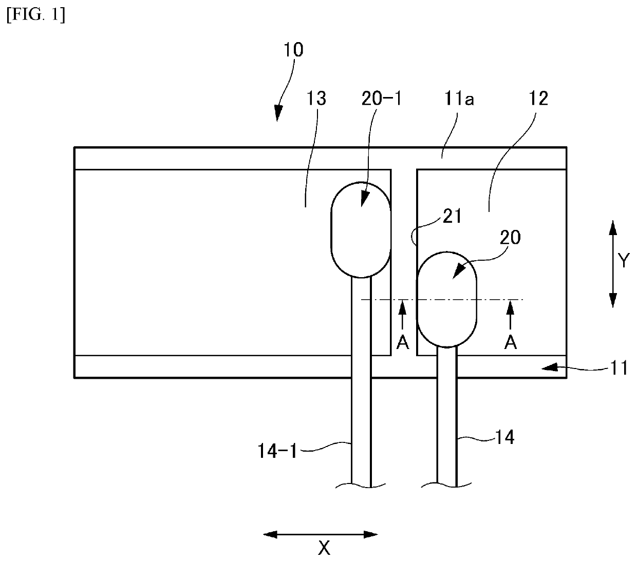
[0033]As shown in FIG. 1, the piezoelectric actuator 10 includes a piezoelectric element 11, an external electrode 12, a wiring member 14 and a conductive joining member 20. Additionally, a driving electrode 13 disposed apart from the external electrode 12 in the X-direction is illustrated in FIG. 1.

[0034]The piezoelectric element 11 is formed including ceramics with piezoelectric properties. Examples of such ceramics may include not only lead zirconate titanate but also a lead-free piezoelectric material such as lithium niobate, lithium tantalate, Bi layered compound and tungsten bronze structure compound.

[0035]The piezoelectric element 11 may have any structure, and a structure as shown in FIG. 2 may be employed, for example. In FIG. 2, the piezoelectric element 11 includes a piezoelectric layer 110 formed in four ceramics layers, an electrode laminate formed in three internal electrode layers 112 alternately laminated, surface electrodes 114 formed on one main surface (an upper ...

second embodiment

[0050]FIG. 6A is a schematic plan view showing a piezoelectric actuator 10A according to a FIG. 6B is a cross-sectional view taken along a line D-D in FIG. 6A. FIG. 6C is an enlarged view showing a Q-portion in FIG. 6A.

[0051]As shown in FIG. 6A, the piezoelectric actuator 10A according to the second embodiment includes the piezoelectric element 11, the external electrode 12, the wiring member 14 and a conductive joining member 20A.

[0052]Unlike the conductive joining member 20 according to the above-described first embodiment, the conductive joining member 20A extends to the upper surface 11a of the piezoelectric element 11 beyond the edge 21 of the external electrode 12. Not surprisingly, the conductive joining member 20A does not extend to the driving electrode 13.

[0053]Like the above-described conductive joining member 20, the conductive joining member 20A has the air gap (not shown) formed between the external electrode 12 and the wiring member 14 in a region overlapping with th...

third embodiment

[0057]FIG. 7 is a schematic plan view showing a piezoelectric actuator 10B according to a

[0058]As shown in FIG. 7, the piezoelectric actuator 10B according to the third embodiment includes the piezoelectric element 11, the external electrode 12, the wiring member 14 and a conductive joining member 20B.

[0059]Unlike the conductive joining member 20 according to the above-described first embodiment, the conductive joining member 20B extends to an edge 21B of the external electrode 12 in the Y-direction. As exemplified in FIG. 7, the conductive joining member 20B extends to the edge 21B located on a lead-out side of the wiring member 14 among both sides of the external electrode 12 of the conductive joining member 20B in the Y-direction. However, the same configuration may also be realized on an opposite edge 21B. Further, like the second embodiment shown in FIGS. 6A and 6B, the conductive joining member 20B may extend to the upper surface 11a of the piezoelectric element 11 beyond the ...


PUM


Abstract

A piezoelectric actuator 10 includes: a piezoelectric element 11; an external electrode 12 covering partially a first surface 11a of the piezoelectric element 11 in a first direction; a wiring member 14; and a conductive joining member 20 joining the wiring member 14 to the external electrode 12, wherein the conductive joining member 20 has an air gap 70 formed between the external electrode 12 and the wiring member 14 in a region overlapping with the wiring member 14 as viewed in the first direction, and wherein the conductive joining member 20 extends to an edge 21 of the external electrode 12 or extends to the first surface 11a of the piezoelectric element 11 beyond the edge 21 of the external electrode 12.

Description

TECHNICAL FIELD[0001]The present invention relates to a piezoelectric actuator, a vibration generating device and an electronic equipment.BACKGROUND ART[0002]There is known a piezoelectric actuator including a piezoelectric element with a surface electrode (an external electrode) on an upper surface thereof and a wiring member with an end portion electrically connected to the surface electrode via a conductive joining member, wherein an air gap surrounded by the surface electrode, the wiring member and the conductive joining member is formed in a cross section of a connecting portion between the piezoelectric element and the wiring member (for example, see Patent Literature 1).[0003]However, in the piezoelectric actuator disclosed in the above Patent Literature 1, it is difficult to enhance adhesiveness of the conductive joining member to the external electrode while suppressing breakage of the conductive joining member to be caused by vibration of the piezoelectric element. Specifi...

Claims


Application Information

Patent Timeline
Patent Type & Authority Patents(United States)
IPC IPC(8): H01L41/04H01L41/083H01L41/053H01L41/047H01L41/09H04R1/04H04R17/00H10N30/063H10N30/87H10N30/20H10N30/50H10N30/80H10N30/853H10N30/88
CPCH01L41/0475H01L41/042H01L41/0472H01L41/053H01L41/083H01L41/0973H04R1/04H04R17/00H10N30/872H10N30/875H10N30/2047H10N30/50H10N30/88H10N30/802
Inventor ITO, FUMIHISAMATSUI, YUKIHIRO
Owner TAIYO YUDEN KK
Features
  • R&D
  • Intellectual Property
  • Life Sciences
  • Materials
  • Tech Scout
  • Unparalleled Data Quality
  • Higher Quality Content
  • 60% Fewer Hallucinations
Learn More