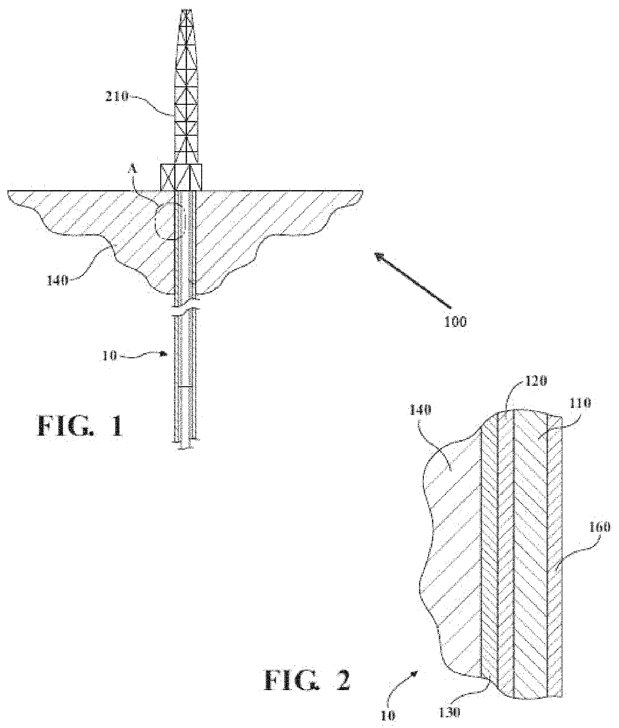
Cement slurries and methods for cementing a casing in a wellbore

a wellbore and cement slurry technology, applied in the direction of wellbore/well accessories, sealing/packing, sustainable waste treatment, etc., to achieve the effects of reducing or preventing interactions, reducing or preventing shale formation, and facilitating adsorption of polyethylene polyamines

Active Publication Date: 2022-11-08
SAUDI ARABIAN OIL CO
View PDF29 Cites 1 Cited by
  • Summary
  • Abstract
  • Description
  • Claims
  • Application Information

AI Technical Summary

Benefits of technology

[0003]Accordingly, there is an ongoing need for improved cement slurries and methods for cementing casings in wellbores in shale formations. The embodiments of the present disclosure include a cement slurry that includes a mixture of polyethylene polyamines. The chemical structure of the polyethylene polyamines may facilitate the adsorption of the polyethylene polyamines onto the surface of clay particles present in shale formations during cementing. The adsorption of the polyethylene polyamines onto the surface of the clay particles may reduce or prevent interactions between the clay particles and the aqueous fluid of the cement slurry. This reduction or prevention of interaction may, in turn, reduce or prevent the hydration of the shale formation. As a result, the cement slurry of the present disclosure may provide a strong bond at the cement-formation interface and reduce the potential for failure of the cement job.

Problems solved by technology

If the cement slurries are unable to perform in a particular temperature or condition, the cement may fail and result in, for example, the loss of zonal isolation.
One factor that may result in cement failure at the cement-formation interface is poor bonding between the cement and the formation.
As a result, the cement may be unable to form a strong bond with the shale formation and the cement may fail.

Method used


Image

  • Cement slurries and methods for cementing a casing in a wellbore

Examples


example 1

[0044]In Example 1, a dispersion recovery test was performed. First, a filter medium (325 mesh screen) was placed in the bottom of the cell of a fluid loss test apparatus (commercially available as Model 7120 from Chandler Engineering) at room temperature (approximately 27° C.). A cement slurry consisting of 355 grams of water, 3 drops of defoamer, and 800 grams of Class G Portland cement particles was then placed in the cell, which was then pressurized up to 1,000 psi. A valve was then opened at the bottom of the cell and the liquid that exited the cell over a duration of 30 minutes was collected.

[0045]Next, two samples of the fluid collected from the cell (that is, cement filtrate) were prepared: a control sample and one that included 15 grams of a mixture of polyethylene polyamines. The mixture of polyethylene polyamines incorporated into the sample was ETHYLENEAMINE E-100 (commercially available from Huntsman). ETHYLENEAMINE E-100 is a mixture of polyethylene polyamines having a...

example 2

[0047]In Example 2, two different cement slurry samples were prepared. The first sample (Comparative Sample A) included only 355 grams of water, 3 drops of defoamer, and 800 grams of cement particles. The second sample (Sample 1) was prepared by mixing 355 grams of water, 3 drops of defoamer, 15 grams of ETHYELNE E100, and 800 grams of cement particles. It should be noted that the cement particles were Class G Portland cement particles. It should be further noted that the specific defoamer used should not have an effect on the rheology of the cement slurry samples so long as it is suitable for use with cement slurries. After preparing the samples, the rheology of both samples was measured at room temperature (RT) using a viscometer (commercially available as Model 35 from Fann Instrument Company). The composition and rheology of each sample are listed in Table 2.

[0048]

TABLE 2Comparative Sample Sample A1CompositionWater (g)355355Defoamer (drops)33Mixture of Polyethylene —15Polyamines...


PUM

PropertyMeasurementUnit
weight percentaaaaaaaaaa
densityaaaaaaaaaa
weight percentaaaaaaaaaa

Abstract

According to one or more embodiments of the present disclosure, a cement slurry includes cement particles, an aqueous fluid in an amount of from 10 wt. % to 70 wt. % relative to the total weight of the cement particles, and a clay stabilizer consisting of one or more polyethylene polyamines having a first structure H2NCH2CH2(NHCH2CH2)xNH2, where x is an integer greater than or equal to 3. The amount of the clay stabilizer may be from 1 wt. % to 10 wt. % relative to the total weight of the cement particles. The average molecular weight of the polyethylene polyamines in the cement slurry having the first chemical structure may be from 200 g / mol to 400 g / mol. All of the polyethylene polyamines in the cement slurry having the first chemical structure may be encompassed in the clay stabilizer. Methods for cementing a casing in a wellbore using the cement slurry are also disclosed.

Description

BACKGROUNDField[0001]The present disclosure relates to natural resource well drilling and, in particular, to cement slurries and methods for cementing a casing in a wellbore.Technical Background[0002]Cement slurries are commonly used in the oil and gas industries, and provide a number of important functions, such as supporting well integrity, supporting the vertical and radial loads applied to casings, and isolating portions of subterranean formations from wellbores. As a result of the significant variety of well locations, cement slurries must be able to consistently perform over a wide range of temperatures and conditions. If the cement slurries are unable to perform in a particular temperature or condition, the cement may fail and result in, for example, the loss of zonal isolation. Generally, the cement may fail in three primary locations: the cement-formation interface, in the bulk cement, and the cement-casing interface. One factor that may result in cement failure at the ceme...

Claims


Application Information

Patent Timeline
Patent Type & Authority Patents(United States)
IPC IPC(8): C09K8/467C04B28/04E21B33/14C04B24/28
CPCC09K8/467C04B24/28C04B28/04E21B33/14C04B2201/20C09K2208/12C09K8/487C09K8/48Y02W30/91C04B14/043C04B14/06C04B18/08C04B18/146C04B2103/46C04B2103/50C04B24/32
Inventor ALKHALAF, SARA A.AL-YAMI, ABDULLAH S.WAGLE, VIKRANTALHELAL, ABDULAZIZ IBRAHIMALSAFRAN, ALI MOHAMMED
Owner SAUDI ARABIAN OIL CO
Why Eureka
Try Eureka