Electrodeposited copper foil and copper clad laminate

Active Publication Date: 2022-11-08
CHANG CHUN PETROCHEMICAL CO LTD
View PDF13 Cites 0 Cited by
  • Summary
  • Abstract
  • Description
  • Claims
  • Application Information

AI Technical Summary

Benefits of technology

[0011]According to the embodiments of the present disclosure, by controlling the characteristic temperature (such as T105.0 wt %) of the elec

Problems solved by technology

Even though the aforementioned blackening treatment may indeed improve the bonding strength between the adjacent boards, the surface of the copper conductive lines m

Method used


Image

  • Electrodeposited copper foil and copper clad laminate
  • Electrodeposited copper foil and copper clad laminate
  • Electrodeposited copper foil and copper clad laminate

Examples


Example

Examples 1-13

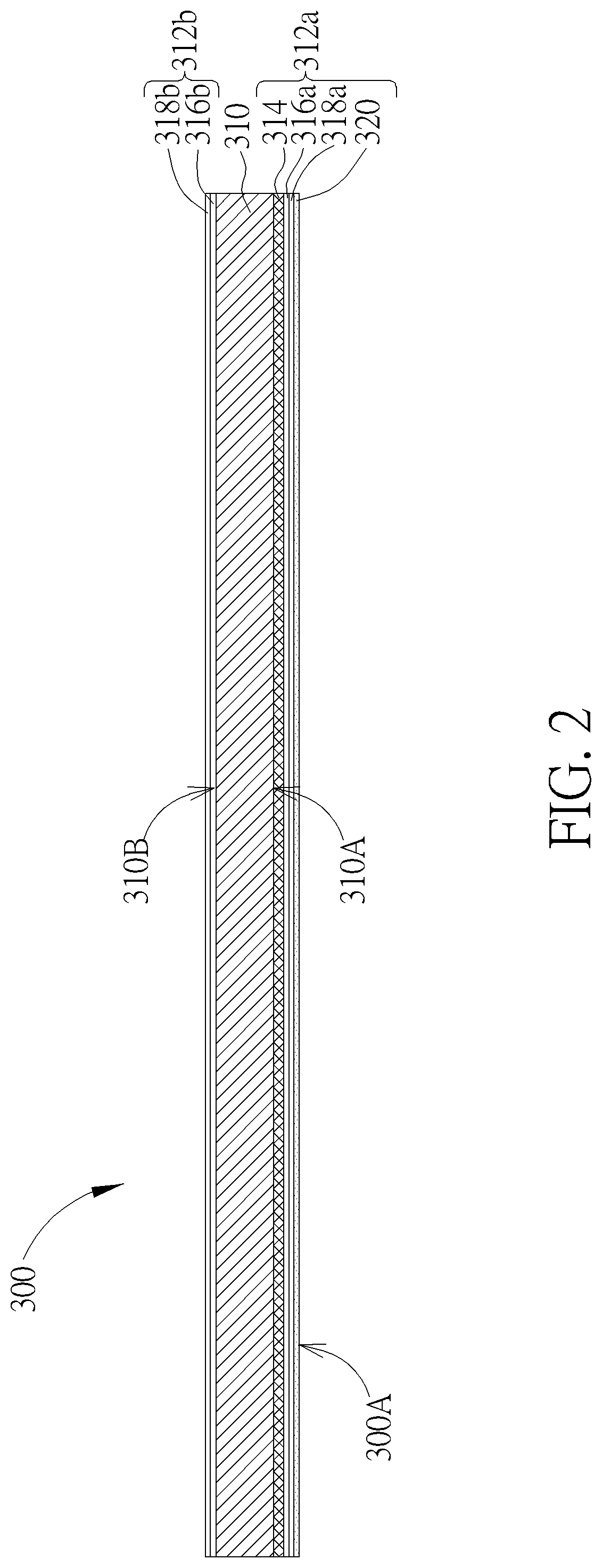
[0112]Examples 1-13 are electrodeposited copper foils, and the fabricating process includes steps A to F in the aforementioned fabricating methods. The fabrication parameters that differ from those of the aforementioned fabricating process are shown in TABLE 1. Specifically, the structures of the electrodeposited copper foils of Examples 1-4, 6-13 are shown in FIG. 2, where a nickel-containing layer, a zinc-containing layer, a chromium-containing layer and a coupling layer are sequentially formed on a roughening layer, and a zinc-containing layer and a chromium-containing layer are sequentially formed on the side of the bulk copper foil without the roughening layer. For Example 5, the electrodeposited copper foil is not provided with the roughening layer, and a nickel-containing layer, a zinc-containing layer, a chromium-containing layer and a coupling layer are sequentially formed on the deposited side of the bulk copper foil. Besides, in Example 5, a zinc-containing l...


PUM


Abstract

An electrodeposited copper foil includes a bulk copper foil. When a weight of the electrodeposited copper foil is increased to 105.0 wt % during a thermogravimetric analysis (TGA) performed on the electrodeposited copper foil at a heating rate of 5° C./min and an air flow rate of 95 mL/min, a heating temperature of the TGA is defined as T105.0 wt % and in a range of 550° C. to 750° C.

Description

BACKGROUND OF THE INVENTION1. Field of the Invention[0001]The present disclosure relates to the field of copper foil, in particular to an electrodeposited copper foil and a copper-clad laminate thereof.2. Description of the Prior Art[0002]With increasing demand for small-sized and thin electronic products capable of transmitting high-frequency signals, the demand for printed circuit boards (PCBs) having conductive lines with miniature lines / spaces (L / S) and having flat contact surfaces between conductive lines and boards is also increasing. Generally speaking, the printed circuit board is a laminated structure including alternately stacked boards, conductive lines and adhesive materials, which may be fabricated by processing a copper foil and a copper-clad laminate. Specifically, the conductive lines may be copper conductive lines, and the adhesive materials may be polymer adhesive materials. The copper conductive lines may be disposed on the surfaces of the boards, and the polymer ...

Claims


Application Information

Patent Timeline
IPC IPC(8): C25D7/04C25D1/04H05K3/14C25D5/00C25D5/12C25D7/06B32B15/01B32B15/08
CPCC25D1/04B32B15/01B32B15/08C25D5/12C25D5/605C25D7/0614H05K3/14B32B2307/30B32B2457/08H05K2203/0726Y10T428/12431B32B15/04B32B15/043B32B15/20B32B33/00H05K3/382C25D3/38C25D5/14C25D3/12C25D3/22C25D3/08H05K3/022H05K1/188Y02E60/10
Inventor LAI, YAO-SHENGCHOU, JUI-CHANG
Owner CHANG CHUN PETROCHEMICAL CO LTD
Why Eureka
Try Eureka