Turbine stator vane comprising an inner cooling wall produced by additive manufacturing

Active Publication Date: 2022-11-08
SAFRAN HELICOPTER ENGINES
View PDF16 Cites 0 Cited by
  • Summary
  • Abstract
  • Description
  • Claims
  • Application Information

AI Technical Summary

Benefits of technology

[0024]The distributor vane may include a hook, in particular at the outer platform, allowing to connect the vane to a turbine ring, and the inner wall can be radially superimposed on the hook, in particular on the front end of the hook. Advantageously, the axial space requirement of the vane can thus be reduced.

Problems solved by technology

In the latter case, the connection between the insert 2 and the distributor is permeable, which then causes a leak at this interface which reduces the efficiency of the cooling.
Moreover, mounting the insert may require cumbersome arrangements.
Furthermore, the insert solution is expensive.
Welding is an expensive operation, especially if the weld is continuous, and depending on the substrate, it may include microcracks.
Adjusting the shapes in contact is also expensive.
In addition, the inserts must be pierced, which complicates their implementation.

Method used


Image

  • Turbine stator vane comprising an inner cooling wall produced by additive manufacturing
  • Turbine stator vane comprising an inner cooling wall produced by additive manufacturing
  • Turbine stator vane comprising an inner cooling wall produced by additive manufacturing

Examples


Embodiment Construction

[0021]The purpose of the invention is therefore to at least partially remedy the needs mentioned above and the disadvantages relating to the embodiments of the prior art.

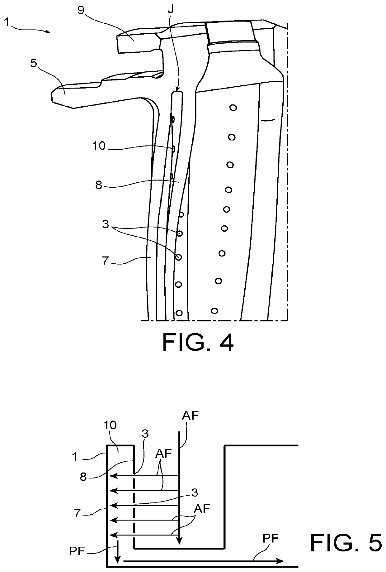
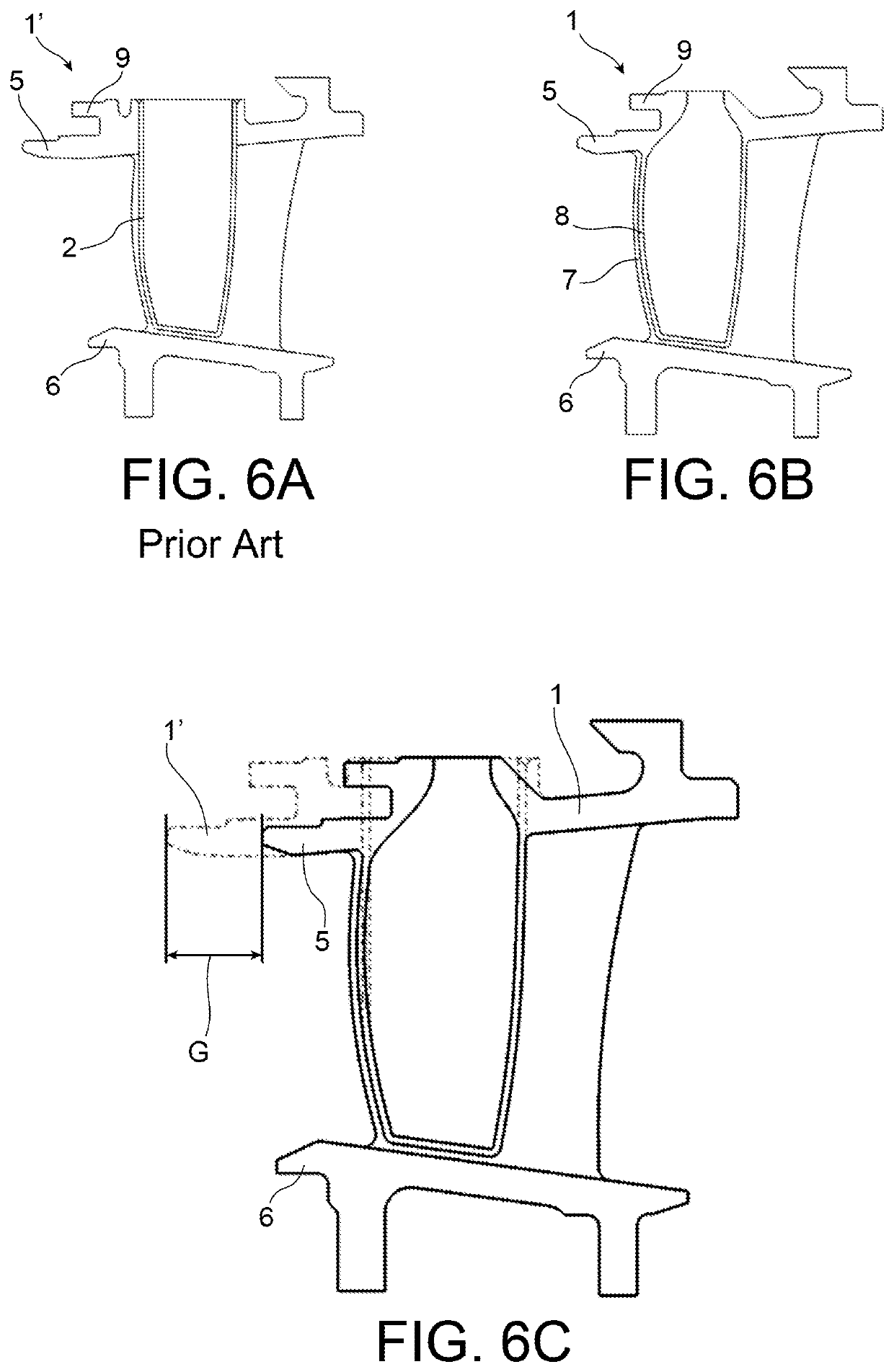
[0022]The object of the invention is thus, according to one of its aspects, a turbine distributor vane, in particular a high pressure turbine, of a gas turbine engine, including an outer platform and an inner platform between which extends an outer wall, forming an outer skin, characterised in that it includes an inner wall, forming an inner skin, facing the outer wall so as to define an inter-skin cavity between the outer and inner walls, the inner wall including a plurality of cooling orifices for cooling the outer wall by impact, the outer and inner walls being produced by additive manufacturing.

[0023]The distributor vane according to the invention may further include one or more of the following features taken separately or in any possible technical combination.

[0024]The distributor vane may include a hook, in p...


PUM

PropertyMeasurementUnit
distanceaaaaaaaaaa
speedaaaaaaaaaa
temperaturesaaaaaaaaaa

Abstract

A stator vane of a turbine of a gas turbine engine, including an outer platform and an inner platform between which there extends an outer wall forming an outer skin, wherein it includes an inner wall, forming an inner skin, facing the outer wall so as to define an inter-skin cavity between the outer wall and the inner wall, the inner wall including a plurality of cooling orifices for impingement cooling of the outer wall, the outer wall and inner wall being produced by additive manufacturing.

Description

TECHNICAL FIELD[0001]The present invention relates to the general field of turbomachines, and more particularly to the field of turbine distributor vanes, in particular high pressure turbines, of a gas turbine engine.[0002]The invention applies to all types of land or aeronautical turbomachines, and in particular to aircraft turbomachines such as turbojet engines and turboprop engines.[0003]Thus, it relates to a turbine distributor vane of a gas turbine engine, including an inner cooling wall produced by additive manufacturing, a turbine including a plurality of such vanes, a turbomachine including such turbine, as well as a method for manufacturing such a distributor vane.PRIOR ART[0004]A high pressure turbine of a gas turbine engine conventionally includes one or more rows of turbine vanes spaced circumferentially all around the rotor of the turbine. It also comprises a distributor assembly allowing to direct the gas flow from the combustion chamber to the turbine vanes at an appr...

Claims


Application Information

Patent Timeline
Patent Type & Authority Patents(United States)
IPC IPC(8): F01D5/14F01D5/18F01D5/28B33Y80/00B33Y10/00
CPCF01D5/147F01D5/187F01D5/28B33Y10/00B33Y80/00F05D2230/20F01D5/284F05D2230/22B22C9/04Y02P10/25Y02T50/60B22F10/28
Inventor HALLOUIN, BAPTISTEBREINING, JEAN-LUCLABERNY, DAMIEN
Owner SAFRAN HELICOPTER ENGINES
Why Eureka
Try Eureka