Eureka AIR delivers breakthrough ideas for toughest innovation challenges, trusted by R&D personnel around the world.

Catalyst-coated membrane having a laminate structure

a technology of laminate structure and catalyst coating, which is applied in the direction of electrolytes, cell components, electrochemical generators, etc., can solve the problems of presenting significant safety hazards, affecting the performance of pemwe, and not being able to achieve significant safety hazards

Active Publication Date: 2022-11-15
JOHNSON MATTHEY HYDROGEN TECH LTD
View PDF20 Cites 0 Cited by
  • Summary
  • Abstract
  • Description
  • Claims
  • Application Information

AI Technical Summary

Benefits of technology

[0012]Such a CCM offers improved performance in a water electrolyser (due to low ionic resistance across the CCM) as well as reduced safety hazard due to reduced hydrogen crossover. Additionally, the CCM is of high quality (i.e. it can be produced with high reproducibility and consistency, and with minimal defects) and may be manufactured more efficiently. The reasons for this are as follows.
[0145]In this way a CCM may be provided with layers which are properly adhered together without being damaged or experiencing detrimental effects on the CCM or membrane component properties.

Problems solved by technology

The result of any excessive crossover of hydrogen is a combination of molecular H2 and molecular O2 at the anode side, which is a potentially explosive mixture presenting a significant safety hazard, due to the wide explosive range of 5-95% H2 in O2.
Thus although improved performance would be obtained by the use of a thinner PEM in PEMWEs, in practice this has not been possible because of the increased hydrogen crossover and the resultant safety risk.
Traditionally, PEM thickness in PEMWEs are greater than 100 μm (for example Nafion™ N115 (thickness 127 μm) or Nafion™ N117 (thickness 183 μm) are used)) to reduce the level of hydrogen crossover but the concomitant increase in ionic resistance severely limits PEMWE performance.

Method used


Image

  • Catalyst-coated membrane having a laminate structure
  • Catalyst-coated membrane having a laminate structure
  • Catalyst-coated membrane having a laminate structure

Examples


example 1

ration

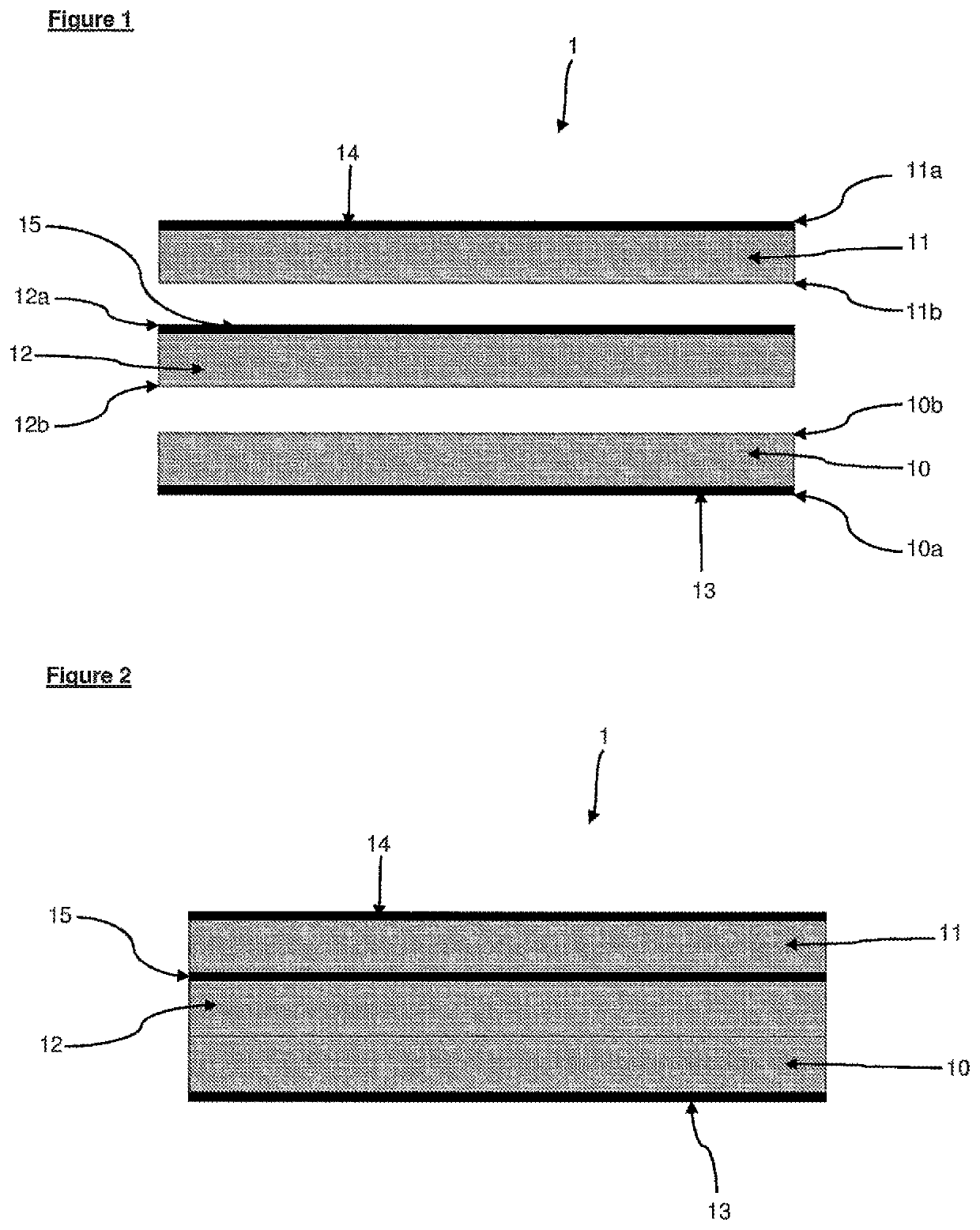
[0175]CCM 1 was prepared using three individual membrane components, Each membrane component had a nominal thickness of 17 μm, comprised a 900 EW Flemion™ ionomer from Asahi Glass Group with e-PTFE reinforcement and had a ceria hydrogen peroxide scavenger catalyst coated on one side. A cathode catalyst layer comprising Pt black in a dispersion of ionomer (aqueous Nafion 1100EW, 12 wt % w.r.t. Pt) was coated in an amount of 1 mgPt / cm2 onto one of the membrane components, on top of the scavenger catalyst. An anode catalyst layer comprising IrO2 black in a solution of ionomer (aqueous Nafion 1100EW from Chemours Corp, 12 wt % w.r.t. Ir) was coated in an amount of 2 mg Ir / cm2 onto another of the membrane components, on top of the scavenger layer. A recombination catalyst comprising Pd supported on carbon black in a solution of ionomer (Nafion 1100EW, 300 wt % w.r.t. carbon) was deposited onto the final membrane component in an amount of 0.04 mg Pd / cm2, on top of the scavenger cata...

example 2

ser CCM Performance

[0180]Each CCM was tested at 60° C. using an electrolyser test station and a QCF25 cell fixture from Baltic Fuel Cells with parallel flow fields machined out of carbon on the cathodic side and titanium anodic side. The CCMs were assembled between a carbon base gas diffusion layer on the cathodic side (SGL 10BB) and a gold coated porous titanium sinter (Mott) on the anodic side. The assembled MEA was then heated in place using the reactant water passing on the cathodic side which in turn was heated via a tube-in-tube heat exchanger and water bath. The polarisation curves were recorded from 2 A cm−2 down to 0.1 A cm−2 holding at each point for 170 s. The hydrogen in oxygen was measured after cooling the anode exhaust gas with a heat exchanger using a four port thermal conductivity detector (GE-XMTC) with pure oxygen as the reference gas and calibrated against a 10% H2 in N2 reference gas and corrected for the different thermal conductivities of O2 and N2. The crosso...


PUM

PropertyMeasurementUnit
thicknessaaaaaaaaaa
thicknessesaaaaaaaaaa
thicknessaaaaaaaaaa

Abstract

A catalyst-coated membrane (CCM) for use in a water electrolyser, having a laminate structure comprising: a first layer comprising a first membrane component having a cathode catalyst layer disposed on a first face thereof; a second layer comprising a second membrane component having an anode catalyst layer disposed on a first face thereof; and an intermediate layer disposed between the first and second layers, comprising a third membrane component having a recombination catalyst layer disposed on a first face thereof is disclosed. The CCM is useful within a water electrolyser. The recombination catalyst layer reduces the risk associated with hydrogen crossover and allows thinner membranes with lower resistance to be used.

Description

CROSS-REFERENCE TO RELATED APPLICATIONS[0001]This application is the National Stage of International Patent Application No. PCT / GB2017 / 053775, filed Dec. 18, 2017, which claims priority to Great Britain Patent Application No. 1621963.6, filed Dec. 22, 2016, the entire disclosures of both of which are incorporated herein by reference for any and all purposes.TECHNICAL FIELD[0002]The present invention relates generally to catalyst-coated membranes having a laminate structure, and in particular for their use in water electrolysers.BACKGROUND ART[0003]Electrolysis of water, to produce high purity hydrogen and oxygen can be carried out in both alkaline and acidic electrolyte systems and practical devices using both types of electrolyte systems exist as commercial products. Those electrolysers that are acid electrolyte-based typically employ a solid proton-conducting polymer electrolyte membrane (PEM) and are known as polymer electrolyte membrane water electrolysers (PEMWEs). A catalyst-c...

Claims


Application Information

Patent Timeline
Patent Type & Authority Patents(United States)
IPC IPC(8): H01M4/88C25B13/02C25B13/08H01M8/1018C25B1/04C25B9/23C25B9/73C25B11/081C25B11/097
CPCH01M4/881C25B1/04C25B9/23C25B9/73C25B11/081C25B11/097C25B13/02C25B13/08H01M8/1018H01M2300/0082H01M2300/0094C25B11/073H01M4/88H01M8/04082H01M8/04197Y02E60/36Y02E60/50H01M8/1004H01M2008/1095
Inventor PRICE, EMILY ROSEWRIGHT, EDWARD ANTHONY
Owner JOHNSON MATTHEY HYDROGEN TECH LTD
Why Eureka
Eureka Blog
Learn More