Processing equipment and processing technology of gel microsphere material

a gel microsphere and processing equipment technology, applied in the field of gel material processing, can solve the problems of serious abraded position of second magnet, reduced contact between swing rod and second magnet,

Active Publication Date: 2022-11-22
SUZHOU YISHENG OPTICAL MATERIAL CO LTD
View PDF11 Cites 3 Cited by
  • Summary
  • Abstract
  • Description
  • Claims
  • Application Information

AI Technical Summary

Problems solved by technology

Further, the end part of the swing rod is fixedly connected with a flexible contact plate; an elastic plate is fixedly connected between the flexible contact plate and the swing rod; and the flexible contact plate is arranged at the end part of the swing rod, a larger contact area can be achieved when the swing rod abuts against the...

Method used


Image

  • Processing equipment and processing technology of gel microsphere material
  • Processing equipment and processing technology of gel microsphere material
  • Processing equipment and processing technology of gel microsphere material

Examples


embodiment i

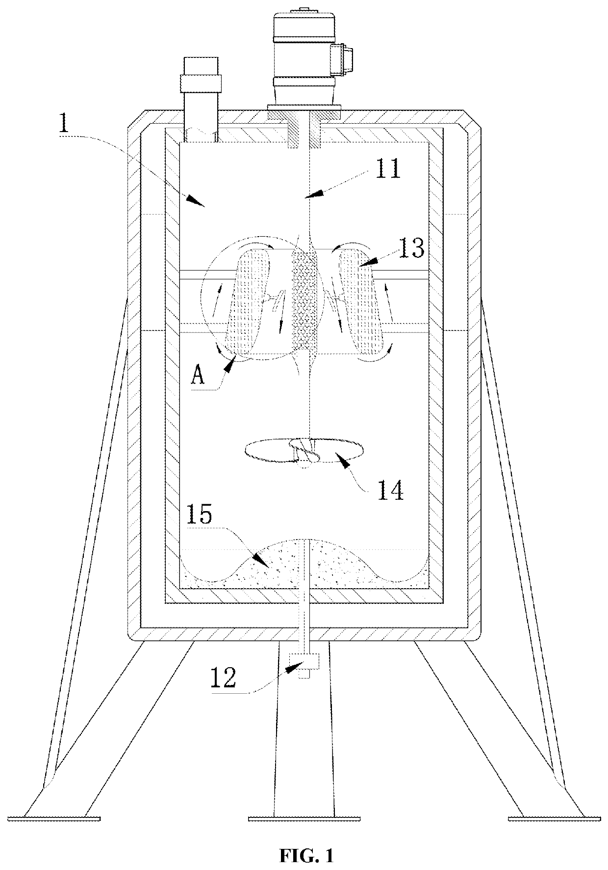
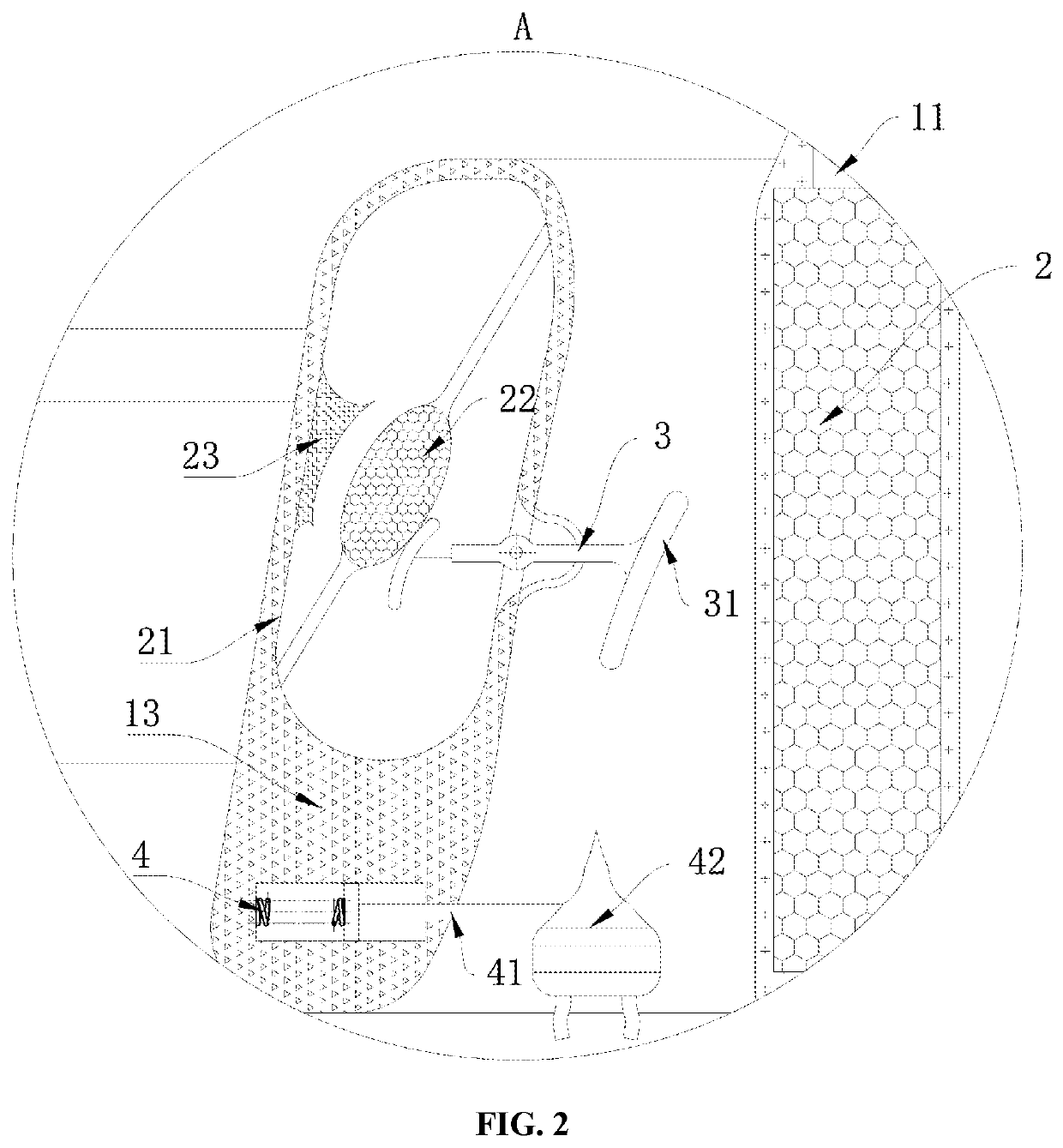
[0040]Referring to FIG. 1 to FIG. 5, processing equipment of a gel microsphere material specifically comprises a mixing barrel 1, wherein a motor is installed at the top of the mixing barrel 1; a rotating rod 11 is arranged in the mixing barrel 1; the rotating rod 11 is fixedly connected to the output end of the motor; the bottom of the rotating rod 11 communicates with a gas conveying pipe 12; a shunting ring 13 is fixedly connected to the inner side wall of the mixing barrel 1; and the middle part of the rotating rod 11 penetrates through the shunting ring 13, and the bottom end of the rotating rod 11 extends to the bottom of the shunting ring 13. Specifically, as shown in FIG. 4, the shunting ring 13 is located in the mixing barrel 1 and is circumferentially arranged in the mixing barrel 1; a fan-shaped impeller 14 is fixedly connected to the bottom of the rotating rod 11, the rotating rod 11 penetrates through the shunting ring 13, and the fan-shaped impeller 14 is located at th...

embodiment ii

[0051]Further, as shown in FIG. 6, contrasted with the first embodiment, as the other embodiment of the present disclosure, the end part of the swing rod 3 is fixedly connected with a flexible contact plate 8; an elastic plate 81 is fixedly connected between the flexible contact plate 8 and the swing rod 3; and the flexible contact plate 8 is arranged at the end part of the swing rod 3, a larger contact area can be achieved when the swing rod 3 abuts against the second magnet 22, so that the vibration effect of the second magnet 22 can greatly act on the swing rod 3, meanwhile, the contact area of the second magnet 22 and the swing rod 3 is increased, and the problem that the position of the second magnet 22 is abraded seriously due to long-time contact between the swing rod 3 and the second magnet 2 can be reduced.

[0052]As shown in FIG. 7, the present disclosure further provides a processing technology of a gel microsphere material; and the processing technology uses the processing...


PUM


Abstract

The present disclosure belongs to the technical field of gel material processing, and discloses processing equipment and a processing technology of a gel microsphere material. The processing equipment comprises a mixing barrel, wherein a motor is installed at the top of the mixing barrel; a rotating rod is arranged in the mixing barrel; the rotating rod is fixedly connected to the output end of the motor; a fan-shaped impeller is installed at the bottom end of the rotating rod; the bottom of the rotating rod communicates with a gas conveying pipe; a shunting ring is fixedly connected to the inner side wall of the mixing barrel; the bottom of the rotating rod is fixedly connected with the fan-shaped impeller; and the gas conveying pipe is arranged at the bottom of the mixing barrel to inflate a raw material solution in the mixing barrel, when bubbles float in the solution, the solution can be stirred, and then under the cooperation of the fan-shaped impeller at the bottom of the rotating rod, the raw material solution of the gel microsphere material is stirred more quickly and more uniformly in the mixing barrel compared with the raw material solution only stirred by the fan-shaped impeller.

Description

CROSS REFERENCE TO RELATED APPLICATION[0001]This patent application claims the benefit and priority of Chinese Patent Application No. 202111132782.0 filed on Sep. 27, 2021, the disclosure of which is incorporated by reference herein in its entirety as part of the present application.TECHNICAL FIELD[0002]The present disclosure belongs to the technical field of gel material processing, and specifically relates to processing equipment and a processing technology of a gel microsphere material.BACKGROUND ART[0003]Gel microspheres, also known as microspherical aerogels and different from common bulk aerogels, belong to a new material of special structure, and are constructed by nanoscale materials in microscale dimensions (typically between 1-1000 μm).[0004]Some technical schemes about gel materials also appear in the prior art, for example, a Chinese patent with the publication number of CN1142221C discloses a thermotropic shape memory gel material and a preparation method thereof, and t...

Claims


Application Information

Patent Timeline
IPC IPC(8): B01J13/00B01J19/18B01F33/453B01J2/04B01F33/40
CPCB01J2/04B01J13/0091B01F33/453B01J19/18B01D19/0078B01J13/02B01F31/445B01F31/449B01F33/402B01F33/405B01F33/406B01F27/861B01J13/0052
Inventor ZHAO, JIANGTIAN, DAWEIZHU, JIANFEISHEN, DONGZHAO, XIN
Owner SUZHOU YISHENG OPTICAL MATERIAL CO LTD
Why Eureka
Try Eureka