Electronic switch with current regulation

Active Publication Date: 2022-11-22
SIEMENS AG
View PDF14 Cites 0 Cited by
  • Summary
  • Abstract
  • Description
  • Claims
  • Application Information

AI Technical Summary

Problems solved by technology

However, this type of switching element of a power conver

Method used


Image

  • Electronic switch with current regulation
  • Electronic switch with current regulation
  • Electronic switch with current regulation

Examples


Embodiment Construction

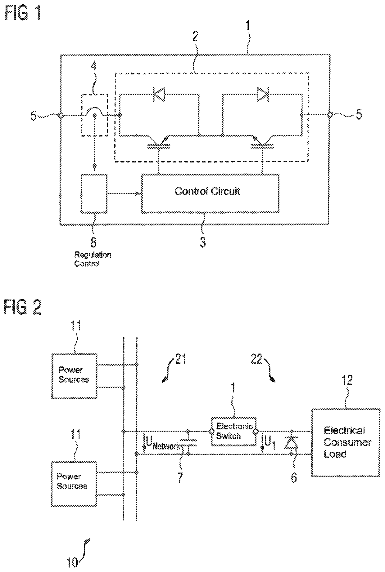
[0036]FIG. 1 shows an electronic switch 1. This has a semiconductor switch 2 which with its two semiconductors can carry and disconnect a current in both directions. The semiconductor switch 2 with its two semiconductors is controlled by a control circuit 3. This control circuit 3 enables the semiconductor switch 2, and thus the semiconductors arranged therein, to be operated in a switched-on state and by pulse-width modulation. The switched-on state is also known as the conductive state, closed state or ON state. The switched-off state is also known as the nonconductive state, open state or OFF state. In pulse-width-modulated operation the semiconductor switch 2 is pulsed with the pulse frequency. The time ratio of switched-on state to switched-off state gives the output voltage at the output of the electronic switch 1 on average over time. The ratio of length of time of the switched-on state to period duration (which corresponds to the inverse value of the pulse frequency) is the ...


PUM


Abstract

An electronic switch includes a current sensor and a semiconductor switch having two semiconductors configured to carry and disconnect a current in both directions, and a control circuit configured to operate the semiconductor switch by pulse-width modulation and to determine a phase control factor of the pulse-width modulation as a function of measurement values of the current sensor such that in fault-free operation, the electronic switch remains in the ON state and that two limit values exist for protection. The electronic switch is operated by pulse-width modulation when a first one of the two limit values is exceeded, and the electronic switch is switched off when a second one of the two limit values, which is greater than the first limit value, is exceeded. The electronic switch is configured to reduce an edge steepness of a switching edge as the phase control factor decreases.

Description

CROSS-REFERENCES TO RELATED APPLICATIONS[0001]This application is the U.S. National Stage of international Application No. PCT / EP2020 / 053543, filed Feb. 12, 2020, which designated the United States and has been published as International Publication No. WO 2020 / 165215 A1 and which claims the priority of European Patent Application, Serial No. 19157443.3, filed Feb. 15, 2019, pursuant to 36 U.S.C. 119(a)-(d).BACKGROUND OF THE INVENTION[0002]The Invention relates to an electronic switch having a semiconductor switch comprising a control circuit. The invention further relates to a power supply system having an electronic switch of this type. The invention further relates to a method for operating an electronic switch of this type or a power supply system of this type.[0003]One way in which switches are currently used is to enable electrical consumer loads to be isolated from the network in power supply systems. With the aid of the switch it is likewise possible to disconnect parts of a...

Claims


Application Information

Patent Timeline
IPC IPC(8): H03K17/082
CPCH03K17/082H03K17/0822H03K17/166
Inventor GAUDENZ, MARKUS MATTHIAS
Owner SIEMENS AG
Why Eureka
Try Eureka