Flip chip with integrated flux and underfill

a technology of flux and underfill, which is applied in the field of flip chip design, can solve the problems of degrading device performance, affecting device completeness, and affecting device performance,

Inactive Publication Date: 2001-06-07
FRY S METALS INC
View PDF0 Cites 27 Cited by
  • Summary
  • Abstract
  • Description
  • Claims
  • Application Information

AI Technical Summary

Benefits of technology

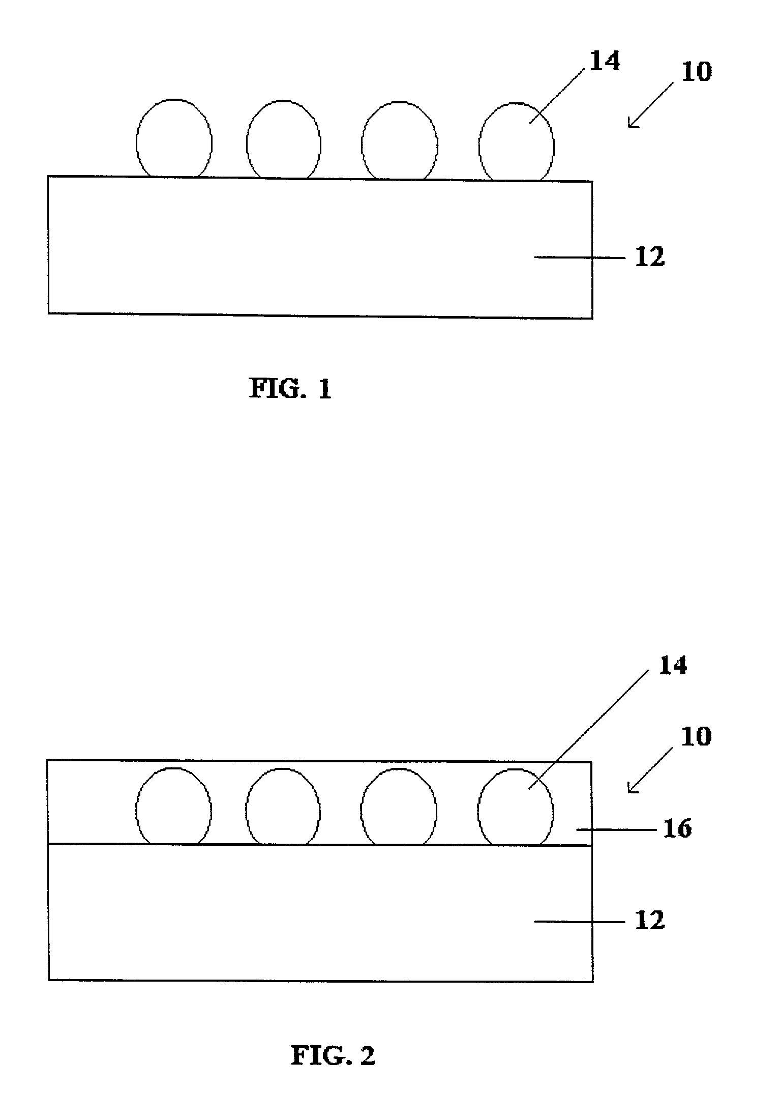
0015] Lastly, the invention relates to a process for affixing a flip chip to a circuit board. The method involves providing a printed circuit board having a plurality of solderable contact sites on a surface, providing an integrated circuit chip of the type described above (i.e., a chip having solder bumps and a flux-integrated underfill material present on its surface), and positioning the integrated circuit chip relative to the printed circuit b

Problems solved by technology

Tolerances in devices using flip chip technology are critical, as the spacing between individual devices as well as the spacing between the chip and the board is typically very small.
One problem associated with flip chip technology is that the chips, the solder and the material forming the circuit board often have significantly different coefficients of thermal expansion.
As a result, differing expansions as the assembly heats during use can cause severe stresses, i.e., thermomechanical fatigue, at the chip connections and can lead to failures which degrade device performance or incapacitate the device entirely.
Such filled epoxy thermosets therefore reduce the likelihood of device failure resulting from thermomechanical fatigue during operation of the device.
While underfill has solved the thermal mismatch problem for flip chips on printed circuit boards, it has created significant difficulties in the manufacturing process.
Flux is used since the pads on printed circuit boards often oxidize, and since solder bumps on flip chips are always oxidized

Method used


Image

  • Flip chip with integrated flux and underfill

Examples


example 1

[0042] Flux / Underfill Preparation

[0043] 20.4% by weight bisphenol A epoxy resin (Ciba, GT7074) was blended with 24.4% by weight dipropylene glycol methyl ether acetate (Dow). 0.7% by weight polyamide thixotropic agent (King Industries, Disparlon 6650) was dispersed in the epoxy resin solution at 65.degree. C. for 15 minutes. The blend was cooled to 25.degree. C. and 5.4% by weight 1,4-cyclohexane dicarboxylic acid, 0.4% by weight 2,4,6-triamino pyrimidine, 48.5% by weight 5-micron silica filler (LE-05, from Tatsumori Ltd., Tokyo, Japan), and 0.2% by weight epoxy silane (TS-100 from OSI Specialties, Friendly, W.Va.), were dispersed in the blend at high shear.

example 2

[0044] Flux / Underfill Preparation

[0045] This material was prepared in a manner similar to that of Example 1, however, 25% by weight bisphenol A and 20% by weight dipropylene glycol methyl ether acetate, were substituted for those amounts provided above. 2% by weight hydrogenated castor oil was substituted for the polyamide thixotropic agent. Additionally, following the cooling step, the additives of Example 1 were substituted with the following: 10% by weight adipic acid, 2% by weight 2,4,6-triamino pyrimidine, 40.9% by weight 5-micron silica filler and 0.1% by weight silane.

example 3

[0046] Flux / Underfill Preparation

[0047] This material was prepared in a manner similar to that of Example 1, however, 40% by weight bisphenol A epoxy resin (Shell, Epon 1007F) and 45% by weight dipropylene glycol methyl ether acetate, were substituted for those amounts provided above. 5% by weight hydrogenated castor oil was substituted for the polyamide thixotropic agent. Additionally, following the cooling step, 10% by weight adipic acid was added.


PUM

PropertyMeasurementUnit
Thermoplasticityaaaaaaaaaa

Abstract

A flip chip having solder bumps and an integrated flux and underfill, as well as methods for making such a device, is described. The resulting device is well suited for a simple one-step application to a printed circuit board, thereby simplifying flip chip manufacturing processes which heretofore have required separate fluxing and underfilling steps.

Description

FIELD OF THE INVENTION[0001] The present invention relates to a novel flip chip design. More particularly, the present invention relates to a flip chip which incorporates solder bumps, flux and an underfill material, wherein the flux and underfill are provided by a single material capable of providing both flux and underfill properties.BACKGROUND OF THE INVENTION[0002] In the electronics industry, electrical components such as resisters, capacitors, inductors, transistors, integrated circuits, chip carriers and the like are typically mounted on circuit boards in one of two ways. In the first way, the components are mounted on one side of the board and leads from the components extend through holes in the board and are soldered on the opposite side of the board. In the second way, the components are soldered to the same side of the board upon which they are mounted. These latter devices are said to be "surface-mounted."[0003] Surface mounting of electronic components is a desirable t...

Claims


Application Information

Patent Timeline
IPC IPC(8): H01L21/56H05K3/34
CPCH01L21/563Y10T428/24917H01L2224/274H01L2224/73203H01L2224/83191H01L2224/83856H01L2924/01004H01L2924/01005H01L2924/01013H01L2924/0105H01L2924/01074H01L2924/01082H01L2924/14H01L2924/19041H01L2924/19042H03F2200/504H05K3/3436H05K3/3489H05K2201/10977H01L2924/01006H01L2924/01023H01L2924/01033H01L2224/81191H01L2924/00014H01L2224/16Y10T428/25Y10T428/12569H01L24/29H01L2224/73104Y10T428/31678Y02P70/613H01L2224/0401Y02P70/50
Inventor GILLEO, KENNETH BURTONBLUMEL, DAVID
Owner FRY S METALS INC
Why Eureka
Try Eureka