Thrust dynamic pressure bearing apparatus and method for manufacturing the same

a technology of dynamic pressure bearings and bearings, which is applied in the direction of dynamo-electric components, rotary bearings, shafts and bearings, etc., can solve the problems of substantially deteriorating dynamic pressure characteristics, uneven gaps in the peripheral direction of thrust dynamic pressure bearing sections, and inability to obtain satisfying dynamic pressure characteristics

Inactive Publication Date: 2001-07-05
NIPPON DENSAN CORP
View PDF0 Cites 9 Cited by
  • Summary
  • Abstract
  • Description
  • Claims
  • Application Information

AI Technical Summary

Problems solved by technology

However, when the shaft member 1 and the thrust plate 2 having the chamfer structure described above are used to form a thrust dynamic pressure bearing section, satisfactory dynamic pressure characteristics are not obtained.
When the thrust plate 2 is deformed for the reasons described above, the perpendicularity between the shaft member 1 and the thrust plate 2 may be lost, and the thrust plate 2 cannot remain in parallel with the thrust bearing members 3 and 4, with the result that the dynamic pressure characteristic is substantially deteriorated.
Also, the gaps in the thrust dynamic pressure bearing section become uneven in the peripheral direction.
As a result, the balance of the pumping force generated by the fluid pressurizing means such as the dynamic pressure generation grooves is lost, and a specified float amount cannot be obtained.

Method used


Image

  • Thrust dynamic pressure bearing apparatus and method for manufacturing the same
  • Thrust dynamic pressure bearing apparatus and method for manufacturing the same
  • Thrust dynamic pressure bearing apparatus and method for manufacturing the same

Examples


Embodiment Construction

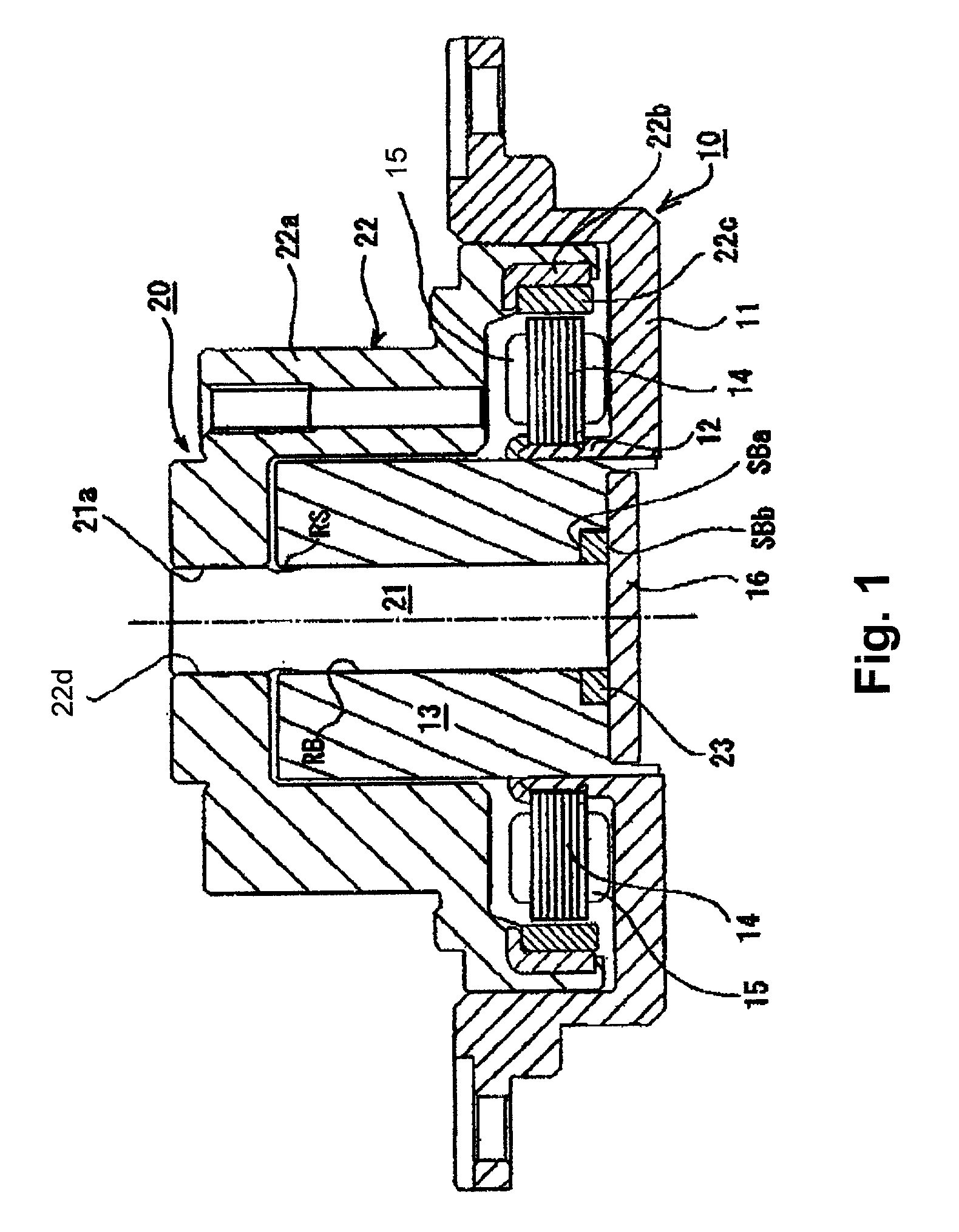
[0028] Embodiments of the present invention will be described with reference to the accompanying drawings. First, a general structure of a hard disc drive apparatus (HDD) having a dynamic pressure bearing assembly is described.

[0029] FIG. 1 shows a cross section of an overall structure of an HDD spindle motor with a rotor shaft. The HDD spindle motor has a stator assembly 10 as a fixed member and a rotor assembly 20 as a rotor member that is mounted over the stator assembly 10 from above in the figure. The stator assembly 10 has a fixing frame 11 that is fixed to a fixing base by screws (not shown). The fixing frame 11 is formed from an aluminum based metal material to reduce its weight, and formed with a circular bearing holder section 12 about the central area of the fixing frame 11. A bearing sleeve 13 in a void cylindrical shape as a fixed bearing member is connected to an internal surface of the bearing holder section 12 by a pressure-insertion or shrink-fit method. The bearing...


PUM


Abstract

A thrust dynamic pressure bearing apparatus includes a shaft member and a thrust plate having a fixing hole that is provided with chamfered sections Ca and Cb at the fixing hole. The shaft member is shrink fitted or pressure inserted in the fixing hole of the thrust plate. The chamfered sections Ca and Cb have axial lengths La and Lb in the axial direction. Dimensional relations of the axial lengths La and Lb in the chamfered sections Ca and Cb are set to be within a specified range to evenly distribute the bonding force of the thrust plate applied to the shaft member along the axial direction.

Description

[0001] 1. Field of the Invention[0002] The present invention relates to a thrust dynamic pressure bearing apparatus that rotatably supports a shaft member and a bearing member in a thrust direction by a dynamic pressure of a lubrication fluid, and a method for manufacturing a thrust dynamic pressure bearing apparatus.[0003] 2. Description of Related Art[0004] In recent years, various proposals have been made for dynamic pressure bearing apparatuses that rotatably support rotor members such as magnetic discs, polygon mirrors, optical discs and the like at high speed. For example, FIG. 13 shows a thrust bearing section of a typical dynamic pressure bearing. The thrust bearing section includes a shaft member 11 that is connected to a thrust plate 2 and a thrust bearing member that is formed from a bearing sleeve 3 and a counter plate 4. The thrust plate 2 has dynamic pressure surfaces disposed opposite, in an axial direction of the shaft member 11, to a dynamic pressure surface of the ...

Claims


Application Information

Patent Timeline
Patent Type & Authority Applications(United States)
IPC IPC(8): F16C17/08F16C33/10H02K7/08
CPCF16C17/045F16C17/08F16C33/107H02K7/085H02K7/086
Inventor GOMYO, MASATOSAICHI, MASAYOSHINARITA, TAKAYUKIMIURA, KAZUSHISATO, MASAAKI
Owner NIPPON DENSAN CORP
Why Eureka
Try Eureka