Method and apparatus for drying substrate plates

a substrate plate and apparatus technology, applied in the direction of lighting and heating apparatus, drying machines with progressive movements, furniture, etc., can solve the problems of difficult to effectively apply the pressure of jet air to completely purge the gathered liquid from the corner portions of the substrate plate, and the inability to slow down the substrate transfer speed through a drying stag

Inactive Publication Date: 2001-08-23
HITACHI ELECTRONICS ENG CO LTD
View PDF0 Cites 40 Cited by
  • Summary
  • Abstract
  • Description
  • Claims
  • Application Information

AI Technical Summary

Problems solved by technology

However, in that corner portion, the substrate plate no longer has a surface for guiding the gathered liquids.
Therefore, especially in a case where a liquid deposits on substrate surfaces in a relatively large quantity, it may become difficult to apply the pressure of jet air effectively for completely purging the gather

Method used


Image

  • Method and apparatus for drying substrate plates
  • Method and apparatus for drying substrate plates
  • Method and apparatus for drying substrate plates

Examples


Embodiment Construction

[0031] Hereafter, the present invention is described more particularly by way of its preferred embodiments with reference to the accompanying drawings. Needless to say, the present invention is not limited to the particular forms shown.

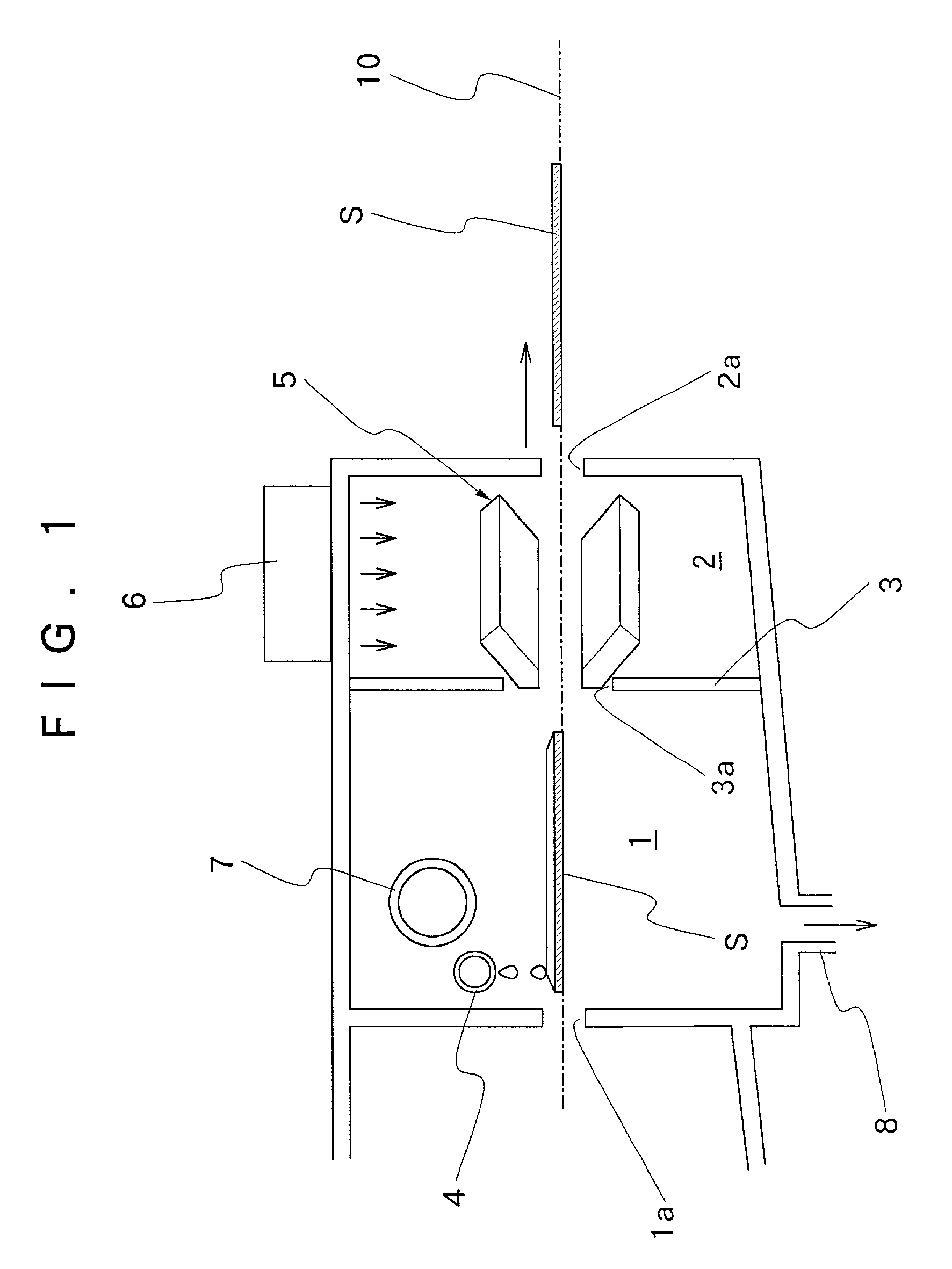
[0032] Referring first to FIG. 1, there is schematically shown a substrate drying stage, in which indicated at S is a substrate plate which is being passed through a preliminary draining stage 1 and a main drying stage 2. The draining and drying stages 1 and 2 are each defined within a housing and separated from each other by a partition wall 3. The draining stage 1 is provided with an entrance opening 1a to receive therethrough substrate plates S which are delivered from a preceding washing stage, while the drying stage 2 is provided with an exit opening 2a for dried substrate plates S. The partition wall 3 is provided with a narrow opening 3a which constitutes part of a path of transfer of the substrate plates S. Provided in the draining stage 1 is ...


PUM


Abstract

While being transferred in substantially horizontal state along a predetermined path of transfer by a conveyer means, a substrate plate is dried by a jet of compressed air which is spurted out from a slit-like mouth of an air knife nozzle crosswise of the entire width of the substrate plate and at a predetermined angle of incidence with respect to a drying surface of the substrate plate to scrape off a liquid. The angle of incidence of jet air is made shallower as soon as the substrate on the conveyer means comes to a point of entry to an air blasting zone and is made deeper at latest when the substrate plate comes to a position immediately before a point of disengagement from the air blasting zone.

Description

[0001] 1. Field of the Art[0002] This invention relates to a method and an apparatus for drying substrate plates, for example, thin substrate plates of a rectangular shape as used for LCD (liquid-crystal display) panels or thin substrate plates of a circular shape.[0003] 2. Prior Art[0004] For instance, a TFT (thin film transistor) type LCD panel generally employs a couple of glass plates as substrates, i.e., a TFT substrate and a color filter substrate. In the fabrication process of TFT substrates, TFT elements are formed on the surface of a glass plate by successively processing same through a number of steps such as formation of a thin film layer, formation of a resist film layer, exposure to light, development, etching and defoliation of the resist film. While being processed through these steps, each TFT substrate needs to be washed and dried repeatedly before or after each step. Similarly, color filters are formed on thin glass plates by a photolithography process or the like,...

Claims


Application Information

Patent Timeline
IPC IPC(8): F26B5/14F26B15/12F26B21/00
CPCF26B5/14F26B15/12F26B21/004
Inventor GOMMORI, KAZUHIKOKINOSHITA, KAZUTOAKIBA, ISAMUSUGIYAMA, MASAO
Owner HITACHI ELECTRONICS ENG CO LTD
Why Eureka
Try Eureka